Tools Required
SA9179NE Dial Indicator
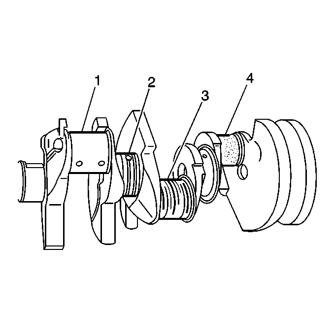
- Clean the crankshaft oil
passages. Remove all debris or restrictions.
- Inspect the crankshaft for the following conditions:
| • | Journals should be smooth
with no signs of scoring, wear or damage. |
| • | Pitting or imbedded material (4) |
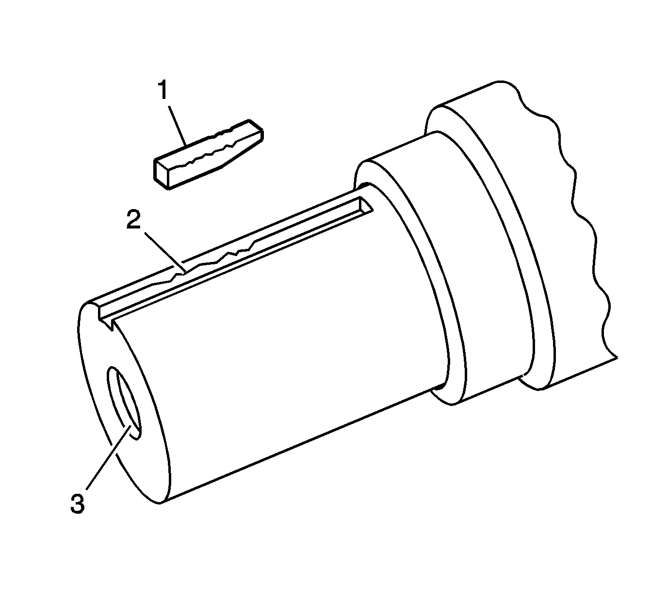
- Inspect the key (1),
keyway (2) and threaded holes (3) for damage.
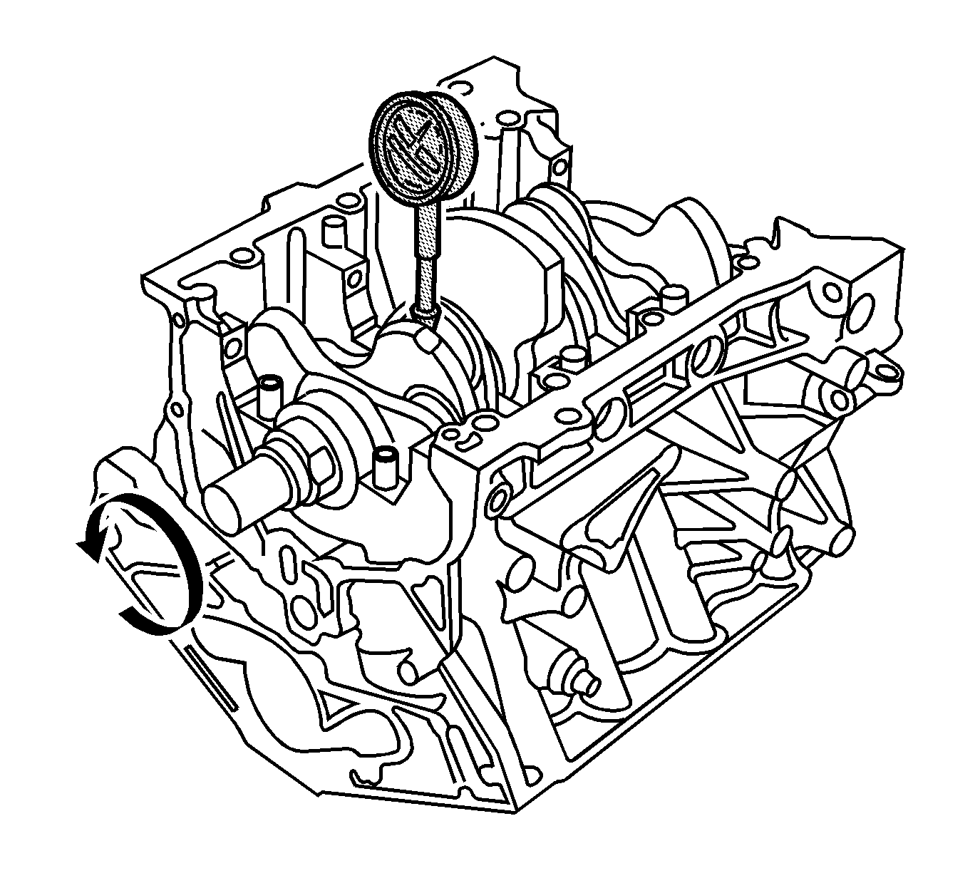
- Install the front and
rear upper main bearings to the engine block.
- Position the crankshaft in the engine block.
- Use the SA9179NE
to measure the main journal runout. Rotate the crankshaft two complete
revolutions. The difference between the journal measurements must not exceed
the service limit.
Specification
| • | Crankshaft total runout - new: 0.02 mm (0.0008 in) |
| • | Crankshaft total runout - service limit: 0.03 mm
(0.0012 in) |
- Measure the main and connecting rod journals for an out-of-round
condition. Measure each journal in 2 places 90 degrees opposite
each other. The difference between the measurements on each journal must
not exceed the service limit.
Specification
| • | Journal out-of-round - new: 0.005 mm
(0.0002 in) |
| • | Journal out-of-round - service limit: 0.01 mm
(0.0004 in) |
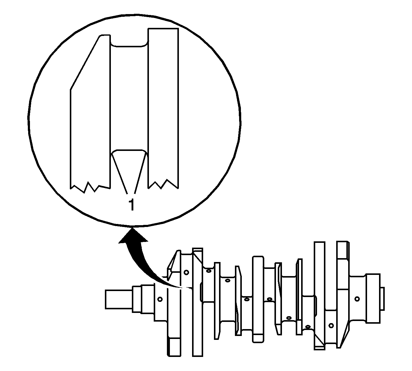
- Measure the main and connecting
rod journals for excessive taper. Measure each journal at the edges (1).
Specification
| • | Journal taper - new: 0.005 mm (0.0002 in) |
| • | Journal taper - service limit: 0.01 mm (0.0004 in) |
Crankshaft End Play Measurement
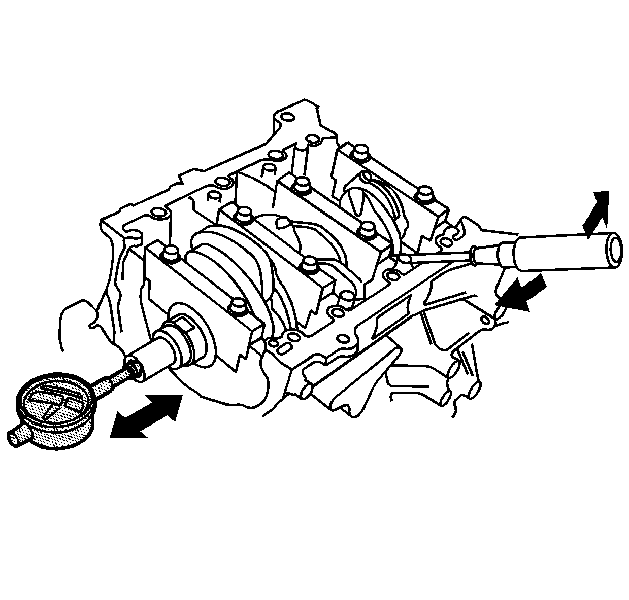
- Push the crankshaft firmly
away from the SA9179NE
and position the tip of the dial indicator against the end of the crankshaft.
- Zero the dial indicator and push the crankshaft firmly toward
the SA9179NE
. If the
end play measurement exceeds the service limit, inspect the thrust washers
and the thrust surface of the crankshaft.
Specification
| • | Crankshaft end play - new: 0.1-0.35 mm (0.004-0.014 in) |
| • | Crankshaft end play - service limit: 0.45 mm (0.018 in) |
- Replace parts as required. The thrust surface of the crankshaft
is a fixed dimension and should not be changed by grinding or shimming.
Connecting Rod Bearing Clearance Measurement
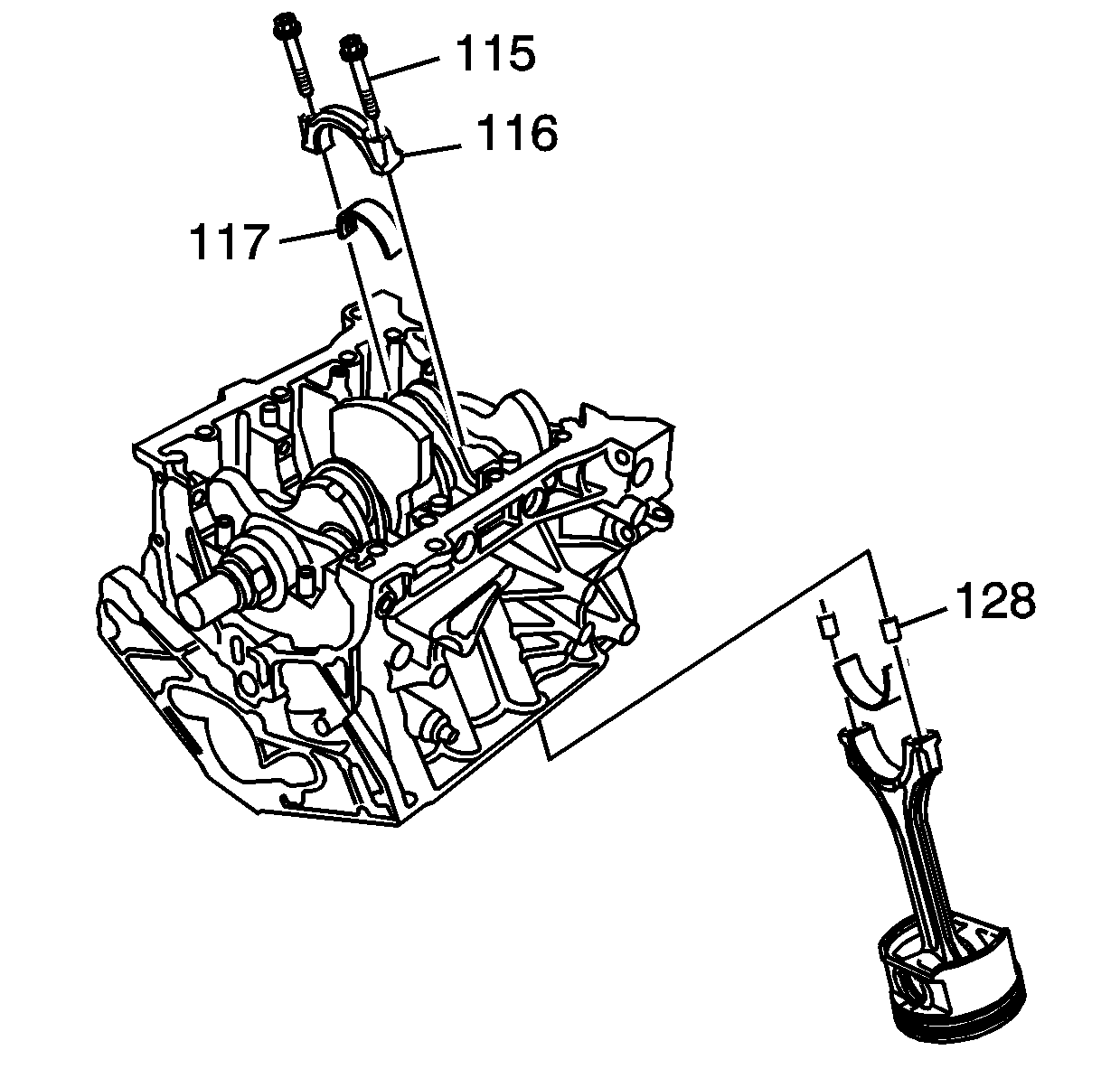
- Remove the connecting
rod bolts (115), cap (116) and lower bearing half (117).
- Clean the crankshaft rod journal and bearing half with a clean
shop towel.
- Place 1 strip of plastic gaging material across the rod journal.
- Install the lower bearing half, cap and bolts. Refer to
Piston, Connecting Rod, and Bearing Installation
.
- Remove the bolts, bearing cap and bearing half. Refer to
Piston, Connecting Rod, and Bearing Removal
.
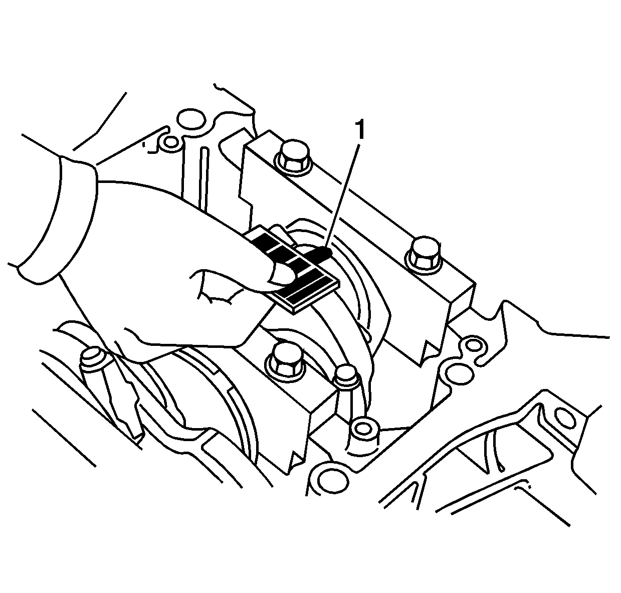
- Measure the widest part
of the plastic gaging material (1).
- If the measurement is too wide or too narrow, remove the upper
bearing half and install a new complete bearing of the same color and measure
again. Do not file, shim or scrape the bearings or caps to adjust clearance.
- If the plastic gaging measurement is still incorrect, try the
next larger or smaller bearing. If the correct clearances cannot be obtained,
replace the crankshaft assembly.
Specification
| • | Connecting rod bearing-to-journal clearance -
new: 0.02-0.044 mm (0.0008-0.0017 in) |
| • | Connecting rod bearing-to-journal clearance -
service limit: 0.05 mm (0.002 in) |
Crankshaft Main Bearing Clearance Measurement
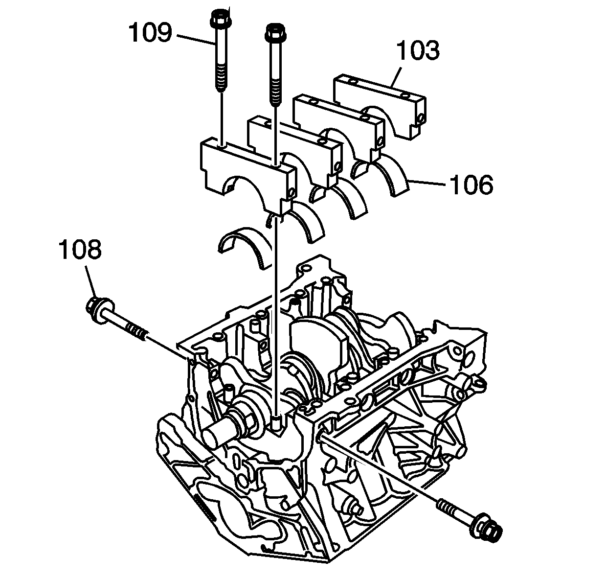
Important: If the bearing clearance measurement procedure is to performed in-vehicle,
the crankshaft must be supported upward with a jack. The weight of the crankshaft
and drive plate will flatten the plastic gaging material and contribute to
an inaccurate measurement.
- Remove the bolts (108 and 109) caps (103) and lower bearings (106).
Refer to
Crankshaft and Bearing Removal
.
- Clean each main journal and bearing half with a clean shop towel.
- Place 1 strip of plastic gaging material across each main journal.
- Install the bearings, caps and bolts. Refer to
Crankshaft and Bearing Installation
.
- Remove the bolts, bearing caps and bearings. Refer to
Crankshaft and Bearing Removal
.
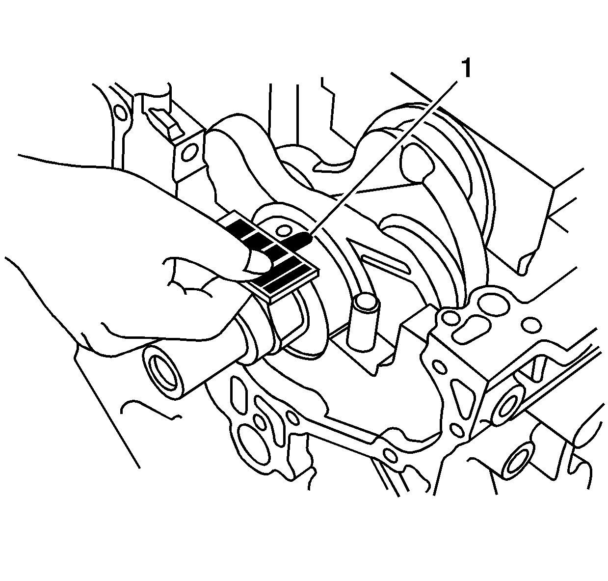
- Measure the widest part
of the plastic gaging material (1).
- If the measurement is too wide or too narrow, remove the crankshaft
and the bearing upper half. Install a new bearing assembly of the same color
and measure again. Do not file, shim or scrape the bearings or caps to adjust
the clearance.
- If the plastic gaging measurement is still incorrect, try the
next larger or smaller bearing. If the correct clearances cannot be obtained,
replace the crankshaft assembly.
Specification
| • | Main bearing-to-journal clearance - new:
0.02-0.044 mm (0.0008-0.0017 in) |
| • | Main bearing-to-journal clearance - service
limit: 0.05 mm (0.002 in) |
Main Bearing Selection
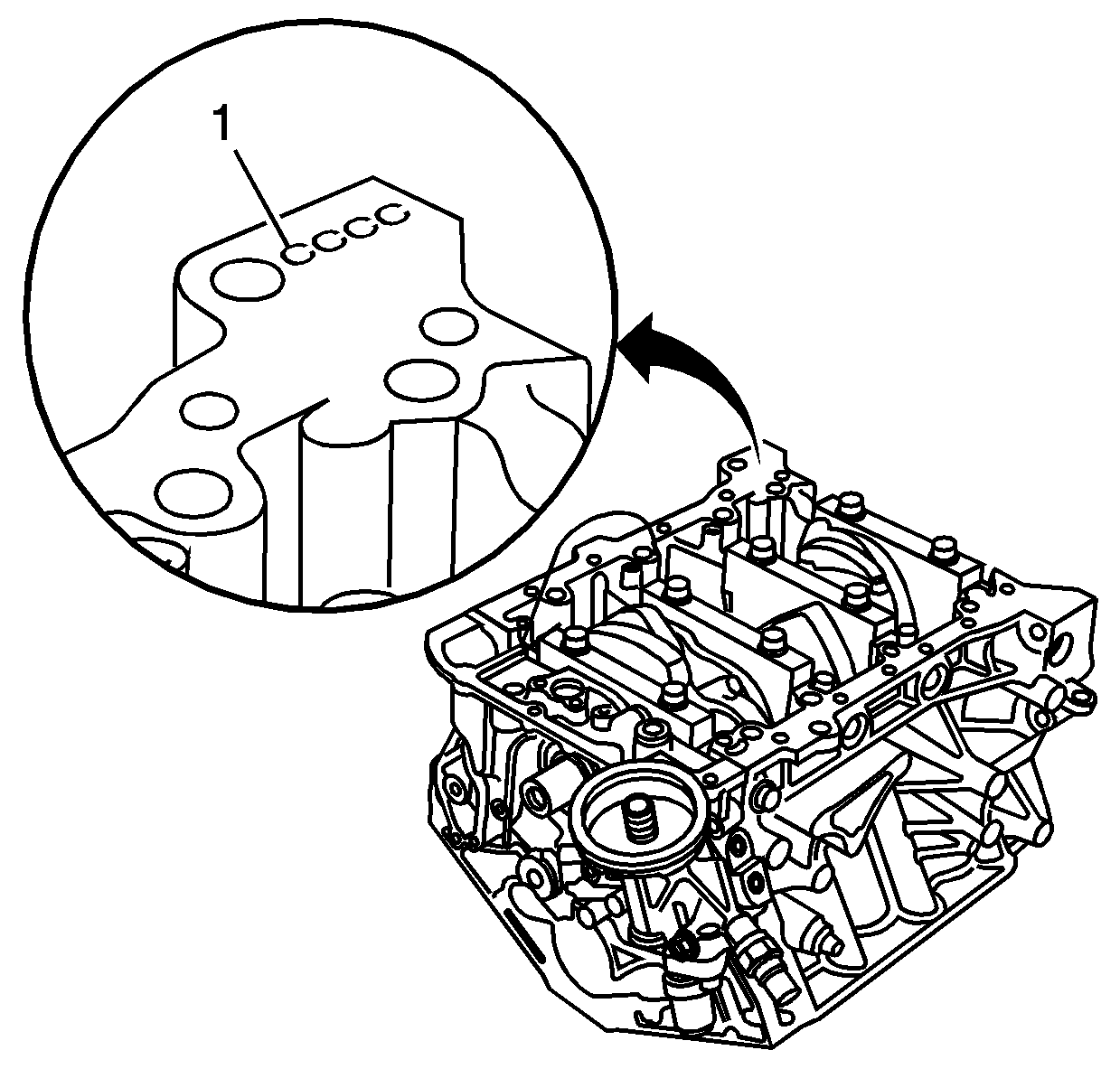
Important: Letters or bars have been stamped on the oil pan surface of the block,
as a code for the inside diameter (I.D.) size of each of the 4 main
journal bores. Use the block and crankshaft markings to choose the correct
size bearings. If the codes are not legible due to dirt or debris, do not
scrub with a wire brush or scraper. Clean them only with solvent or detergent.
- Locate the main journal bore diameter markings on the engine block rear
flange. The first letter or bar (1) identifies crankshaft main journal
number 1.
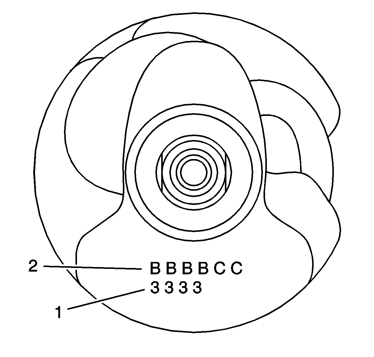
- Locate the main journal
outside diameter (O.D.) markings on the front of the crankshaft. The
first number (1) identifies crankshaft main journal number 1.
- Select the main journal bearings. Refer to
Crankshaft Bearing Selection Specifications
.
Connecting Rod Bearing Selection
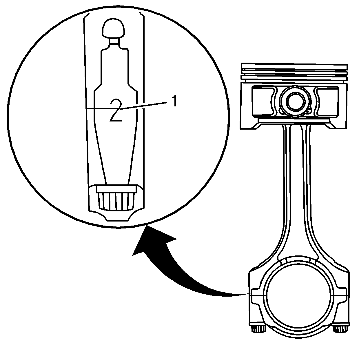
Important:
| • | Each connecting rod falls into 1 of 4 tolerance ranges
from 0.0-0.024 mm (0.0-0.0009 in) in 0.006 mm
(0.0002 in) increments depending on the inside diameter (I.D.)
size of the big end bore. The connecting rod is then stamped with a number
or bar indicating the range. It may be common for the connecting rods on the
engine assembly to be of a different I.D. size range and stamping. |
| • | Numbers or bars have been stamped on the side of each connecting rod (1)
as a code for the I.D. size of the journal end. Use the connecting rod and
crankshaft markings to choose the correct size bearings. If the codes are
not legible due to dirt or debris, do not scrub with a wire brush or scraper.
Clean them only with solvent or detergent. |
- Locate the journal bore diameter marking (1) on the side of the
connecting rod.

- Locate the connecting
journal diameter marking on the front of the crankshaft. The first letter (2)
identifies connecting rod journal number 1.
- Select the connecting rod journal bearings. Refer to
Connecting Rod Bearings Selection Specifications
.


