Tools Required
SA9140E Torque Angle Gage
Removal Procedure
- Disconnect the negative battery cable.
- Remove the intake manifold and spacer. Refer to Intake Manifold Replacement .
- Drain the coolant. Refer to Cooling System Draining and Filling in Engine Cooling.
- Remove the coolant bridge.
- Remove the coolant bridge seals.
- Remove the rear camshaft cover. Refer to Camshaft Cover Replacement - Right Side .
- Disconnect the rear O2 sensor connector.
- Remove the timing belt. Refer to Timing Belt Replacement .
- Remove the camshaft sprockets. Refer to Camshaft Drive Sprocket Replacement .
- Remove the rear timing belt cover. Refer to Timing Belt Rear Cover Replacement .
- Raise the vehicle.
- Disconnect the O2 sensors.
- Remove the front exhaust manifold pipe to the rear exhaust manifold pipe fasteners.
- Remove the rear exhaust manifold pipe to exhaust manifold nuts.
- Pull down the rear exhaust manifold pipe nuts enough to remove the gasket.
- Remove the old gasket and discard.
- Lower the vehicle.
- Remove the exhaust camshaft. Refer to Camshaft Replacement - Right Side .
- Remove the cylinder head bolts.
- Remove the cylinder head.
- Support the engine with the floor jack and block of wood under the oil pan.
- Remove the three bar engine support fixture.
- Remove the cylinder gasket.
- Remove the exhaust manifold
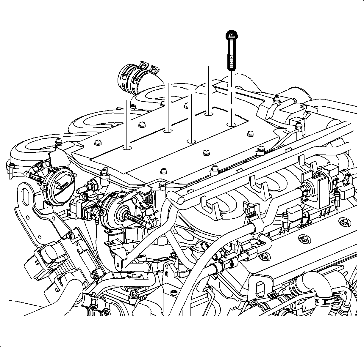
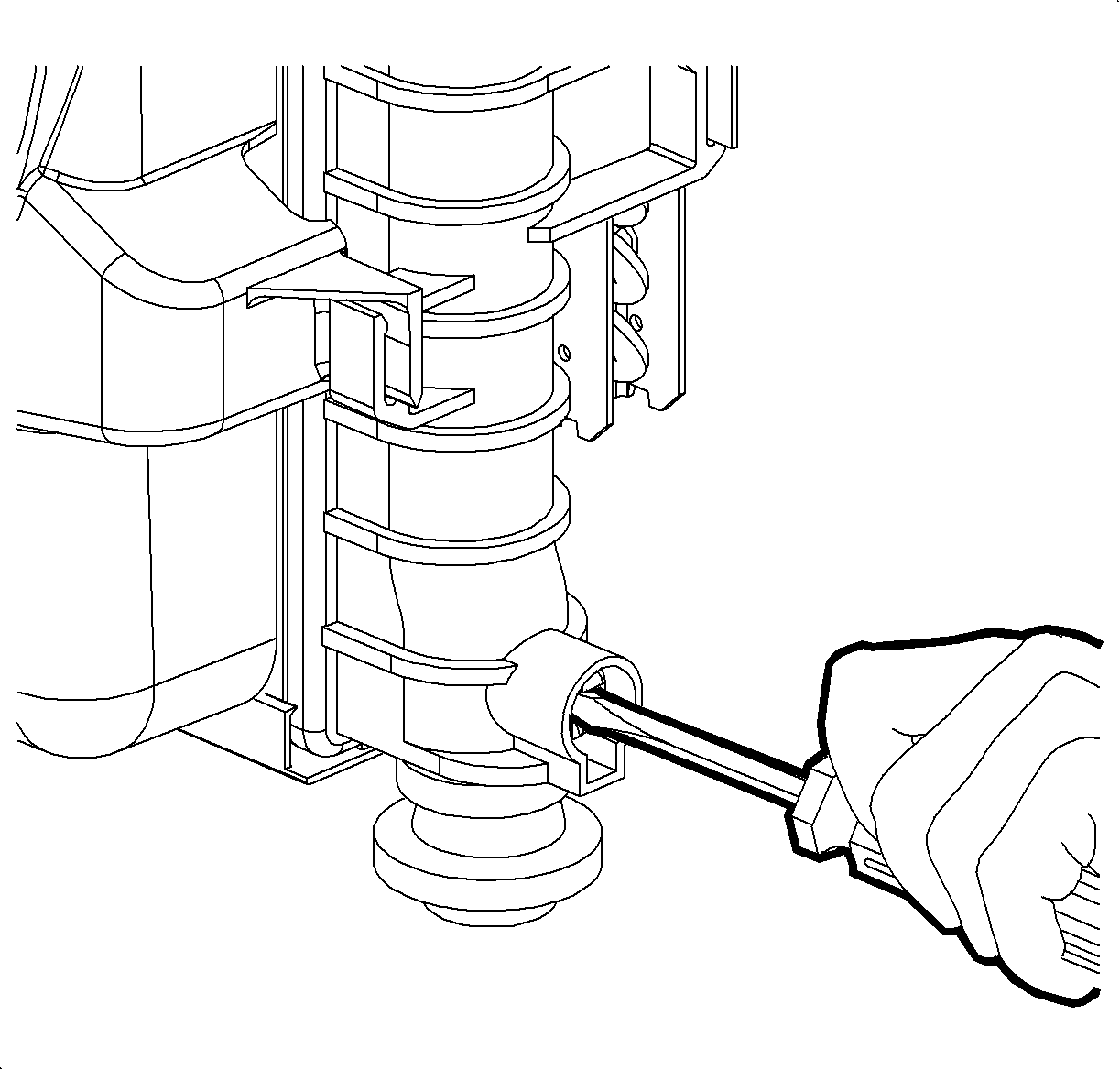
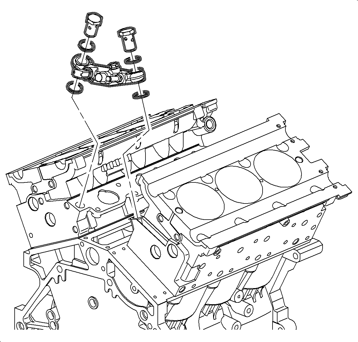
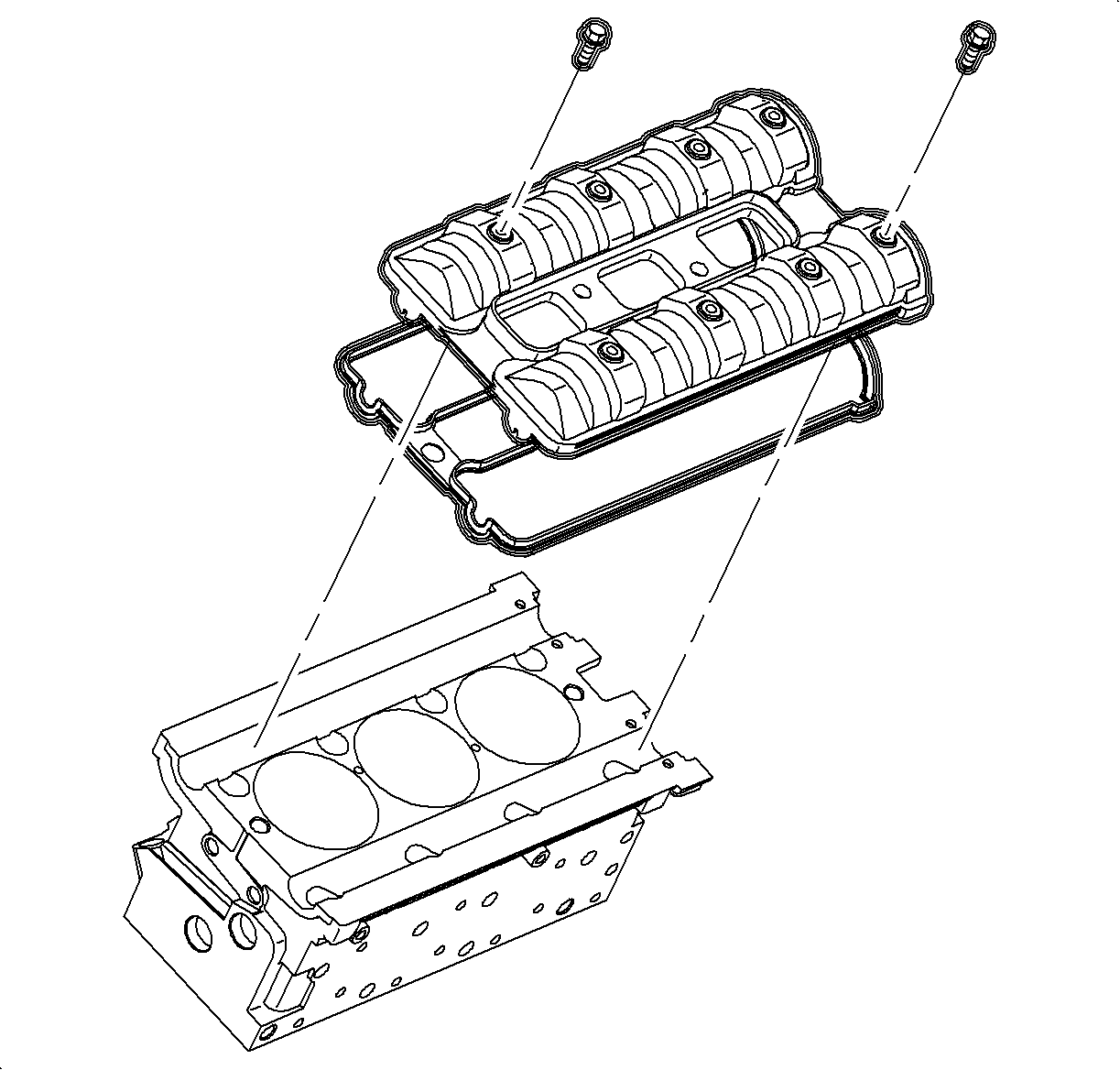
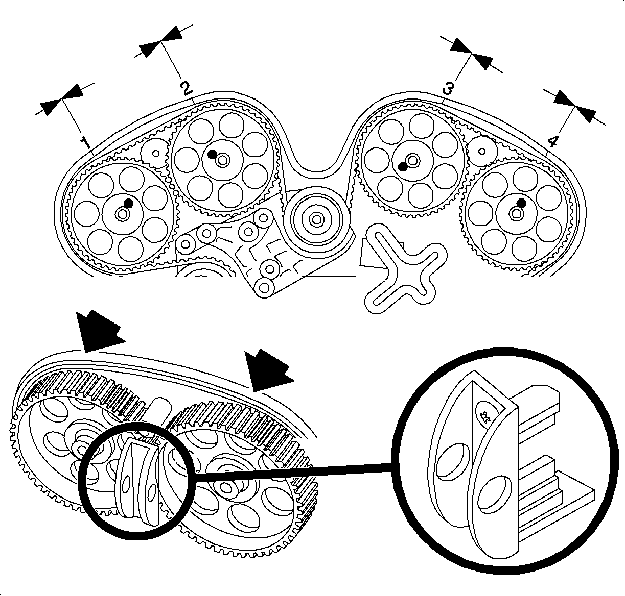
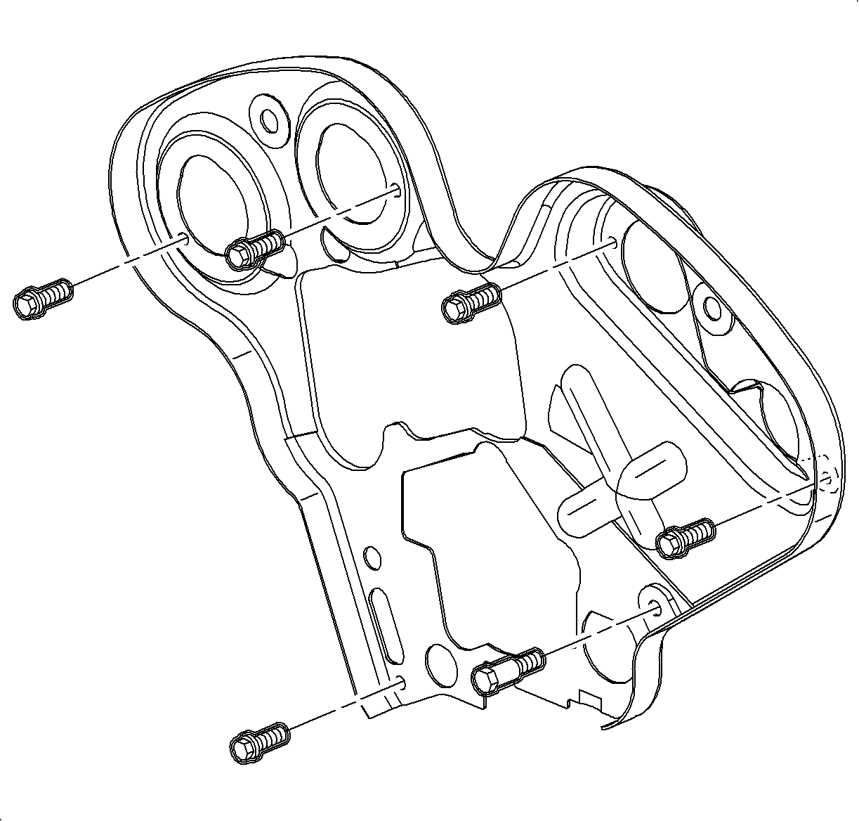
Caution: Ensure that the vehicle is properly supported and squarely positioned. To help avoid personal injury when a vehicle is on a hoist, provide additional support for the vehicle on the opposite end from which the components are being removed.
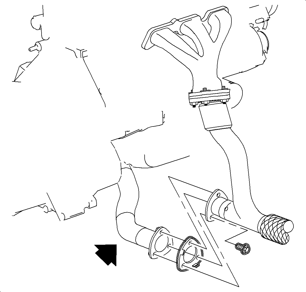
Important: Excessive movement of the pipe can damage the flex pipe.
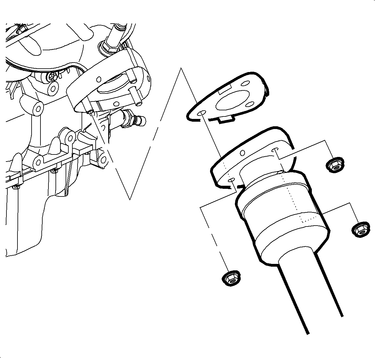
Important: The rear exhaust manifold will stay on the cylinder head during the cylinder head removal.
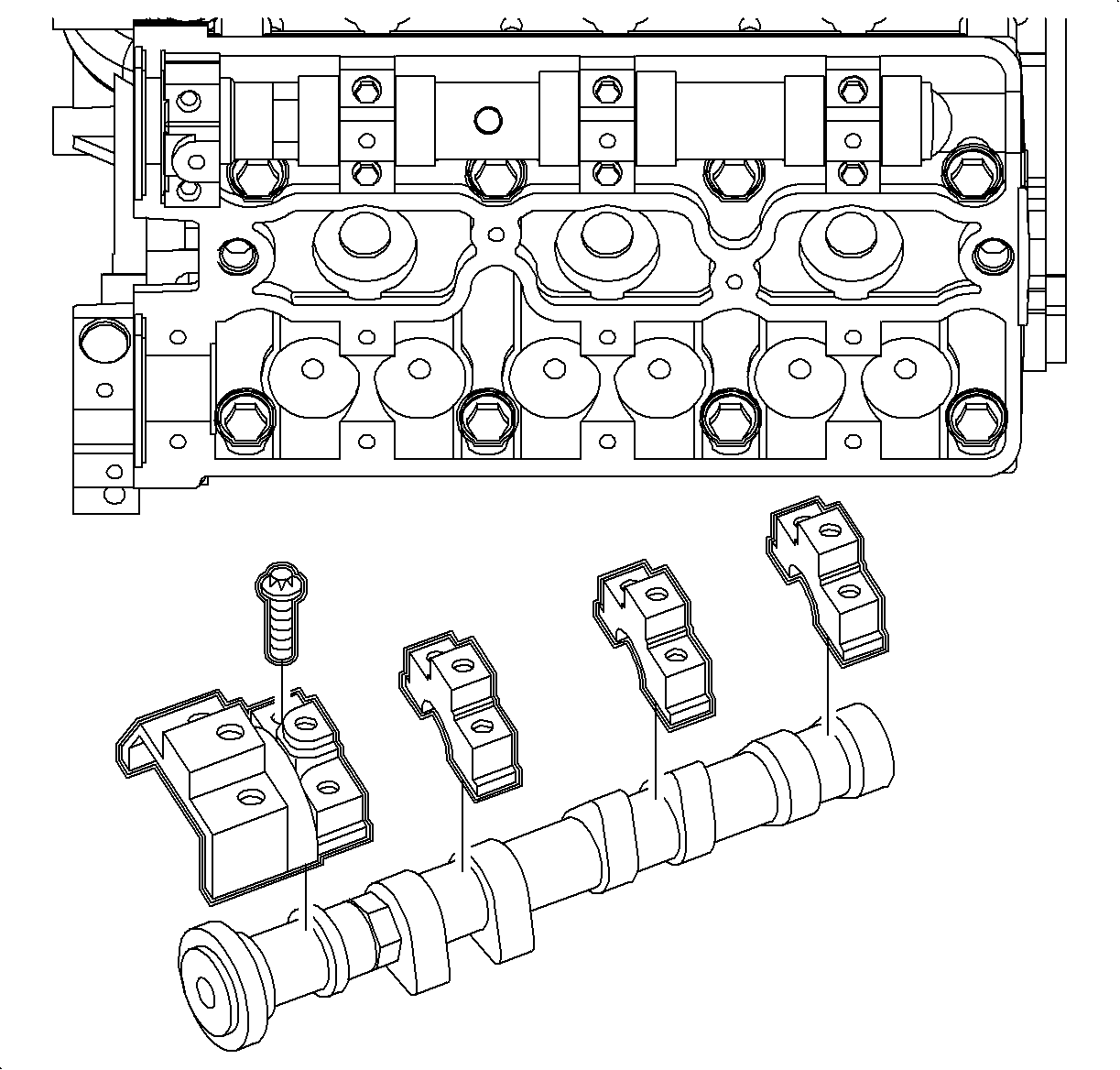
Important: Use new cylinders bolt. The tightening method stretches the bolts to their yield point. Therefore, the cylinder head bolts are not reusable.
Important: The intake camshaft is marked with the letter A and the exhaust camshaft is marked with the letter E.
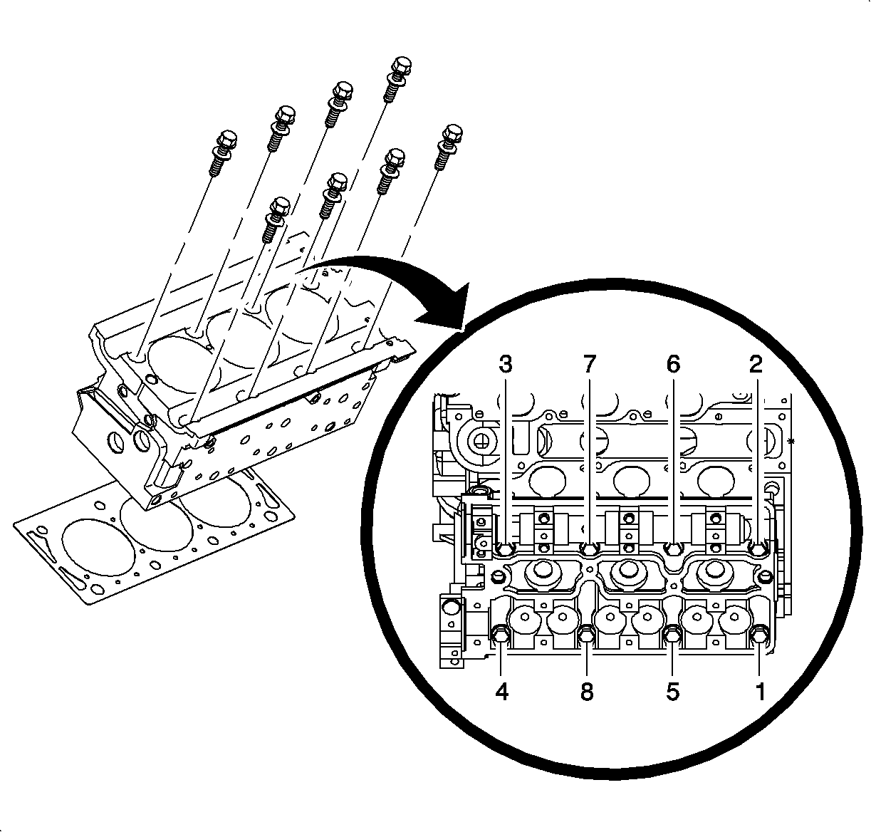
Important: It is not necessary to remove the intake camshaft to access the head bolts.
Important: Use the loosening sequence to remove the cylinder head.
Installation Procedure
- Transfer all components to the new cylinder head if the cylinder head was removed.
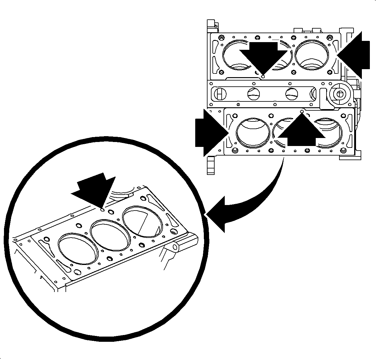
- Install the new cylinder head gasket with the part number imprint toward the top of the engine.
- Install the cylinder head to the engine block ensuring adequate clearance from all wires, components, etc.
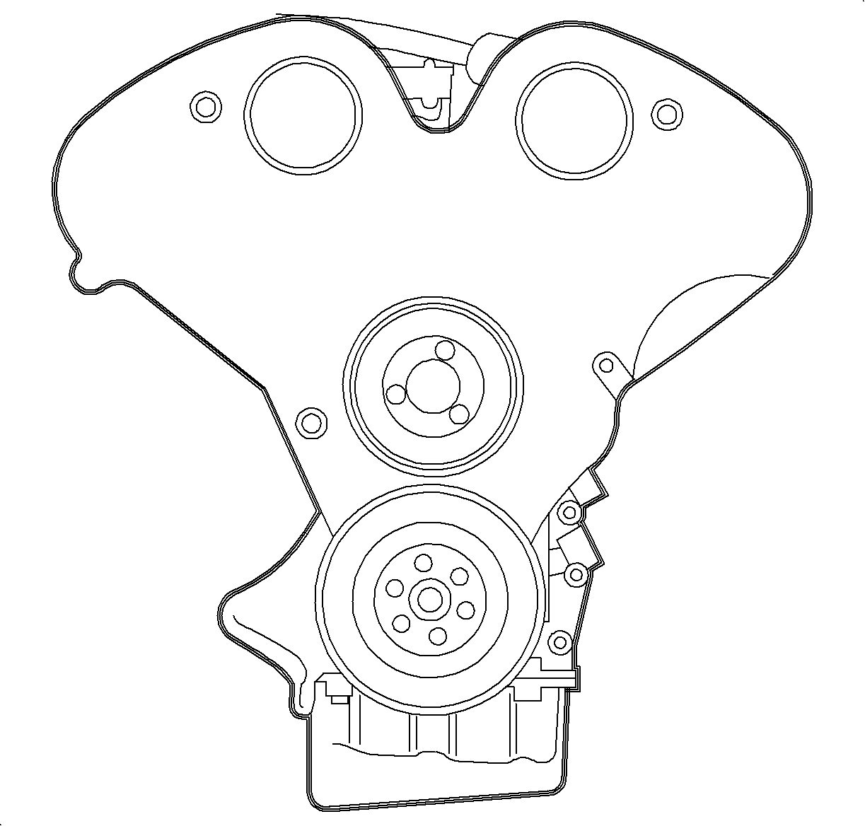
- Install the new cylinder head bolts. Tighten the cylinder head bolts in the proper tightening sequence and in stages.
- First Pass: Tighten the cylinder head bolt to 25 N·m (18 lb ft).
- Second Pass plus 90 degrees
- Third Pass plus 90 degrees
- Fourth Pass plus 90 degrees
- Final Pass plus 15 degrees
- Install the three bar engine support fixture to the 6 Cylinder (L81) B. Refer to the Engine Support Fixture Configurations procedure.
- Install the exhaust camshaft. Refer to Camshaft Replacement - Right Side .
- Install the rear timing belt cover. Refer to Timing Belt Rear Cover Replacement .
- Install the camshaft sprocket. Refer to Camshaft Drive Sprocket Replacement .
- Install the timing belt. Refer to Timing Belt Replacement .
- Install the front timing belt cover. Refer to Timing Belt Front Cover Replacement .
- Remove the three bar engine support fixture.
- Install the rear camshaft cover. Refer to Camshaft Cover Replacement - Right Side .
- Connect the rear O2 sensor connector.
- Properly position the coolant bridge seals on the block.
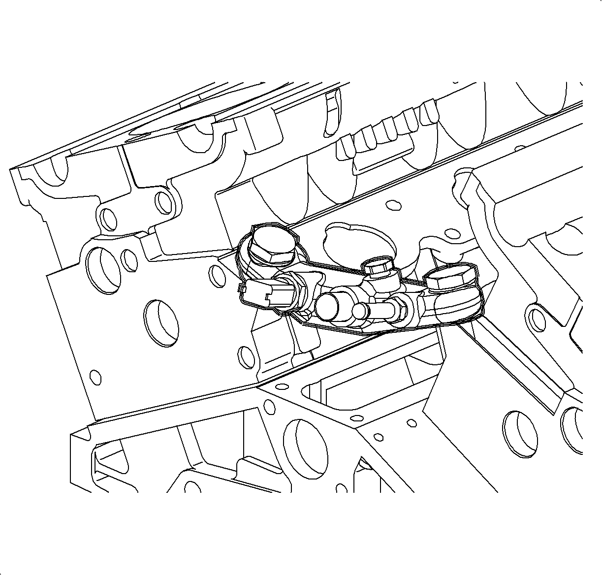
- Install the coolant bridge into position.
- Install the coolant bridge bolts.
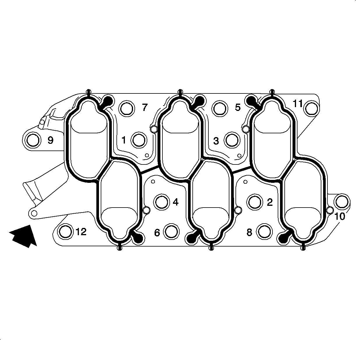
- Install the intake manifold spacer and tighten the bolts in sequence.
- Install the intake manifold. Refer to Intake Manifold Replacement .
- Raise the vehicle.
- Install the exhaust manifold pipe gasket and assembly.
- Install the exhaust manifold pipe nuts.
- Lower the vehicle.
- Refill the coolant. Refer to Cooling System Draining and Filling in Engine Cooling.
- Connect the negative battery cable.
Notice: Refer to Fastener Notice in the Preface section.
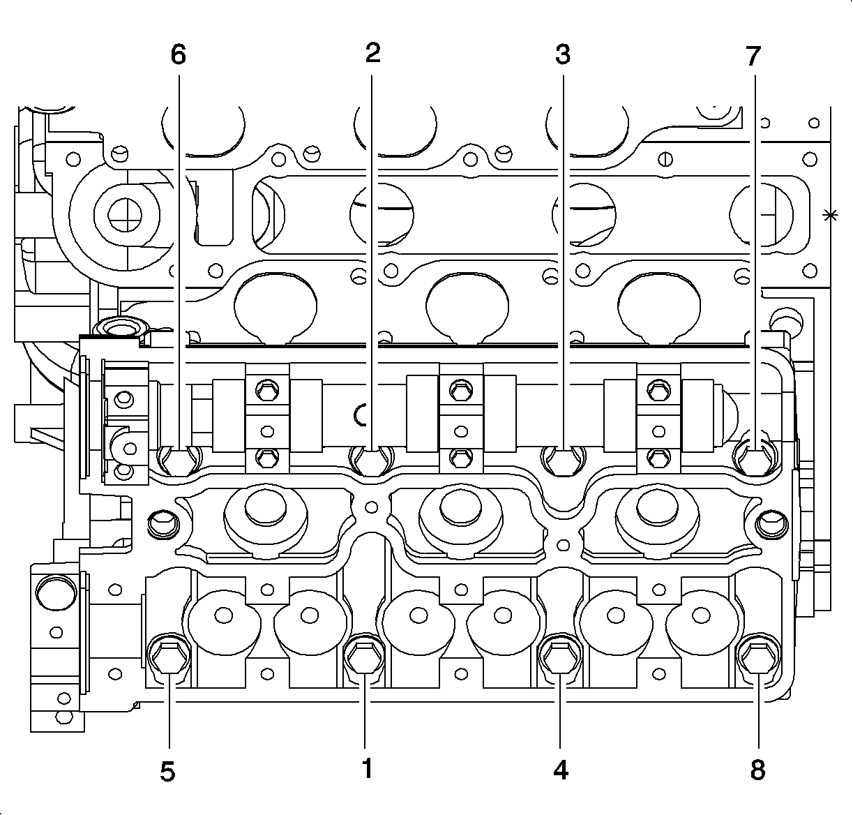
Important: Use new cylinder head bolts. The required tightening method stretches the bolts to their yield point. Therefore, the cylinder head bolts are not reusable.
Use the SA9140E or equivalent to properly tighten the cylinder head bolts. The cylinder head bolts must be torqued in sequence.Tighten


Tighten
Tighten the coolant bridge bolts to 30 N·m (22 lb ft).
Tighten
Tighten the intake manifold spacer bolts to 20 N·m (25 lb ft).


Caution: Ensure that the vehicle is properly supported and squarely positioned. To help avoid personal injury when a vehicle is on a hoist, provide additional support for the vehicle on the opposite end from which the components are being removed.
Tighten
Tighten the exhaust manifold pipe-to-exhaust manifold nuts to 30 N·m (25 lb ft).
Tighten
Tighten the battery terminal bolt to 17 N·m (13 lb ft).
