GM Service Manual Online
For 1990-2009 cars only
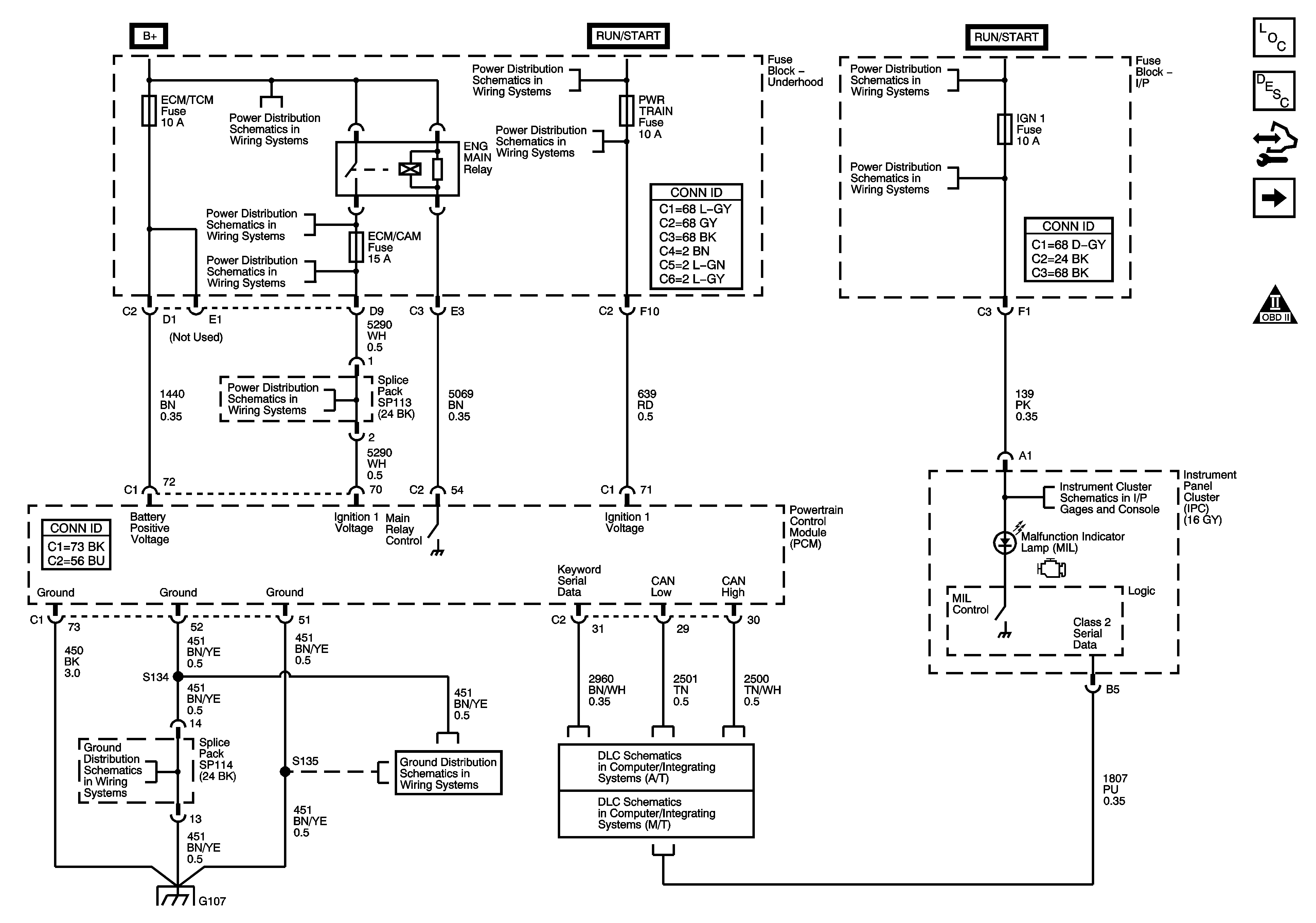
Figure 1:

PCM Power, Ground, Communication and the MIL

Object Number: 1583995  Size: FS
Master Electrical Component List
Powertrain Control Module Description
Control Module References
5-Volt References
Engine Controls Schematic Icons
IGN Fuse and the Ignition Switch Circuits
SUNROOF Fuse, PWR WDW Fuse, 10A ABS Fuse, 20A ABS Fuse, ABS PWR Fuse, HVAC BLOWER Fuse, AUX1 OUTLET Fuse, CIGAR/AUX2 Fuse and the ECM/TCM Fuse
B+ Bussing and the EPS Fuse
ECM/CAM Fuse - L66
ECM/CAM Fuse - L66
BACKUP Fuse, PWR TRAIN Fuse, 10A ABS Fuse and the INJECTORS (L66) Fuse
IGN1 Fuse, BCM(IGN) Fuse, AIR BAG Fuse, EPS Fuse and the CRUISE Fuse
Indicators and Serial Data
G107 and G109 - L66
G107 and G109 - L66
G107 and G109 - L66
L66
DLC Schematic (M/T)
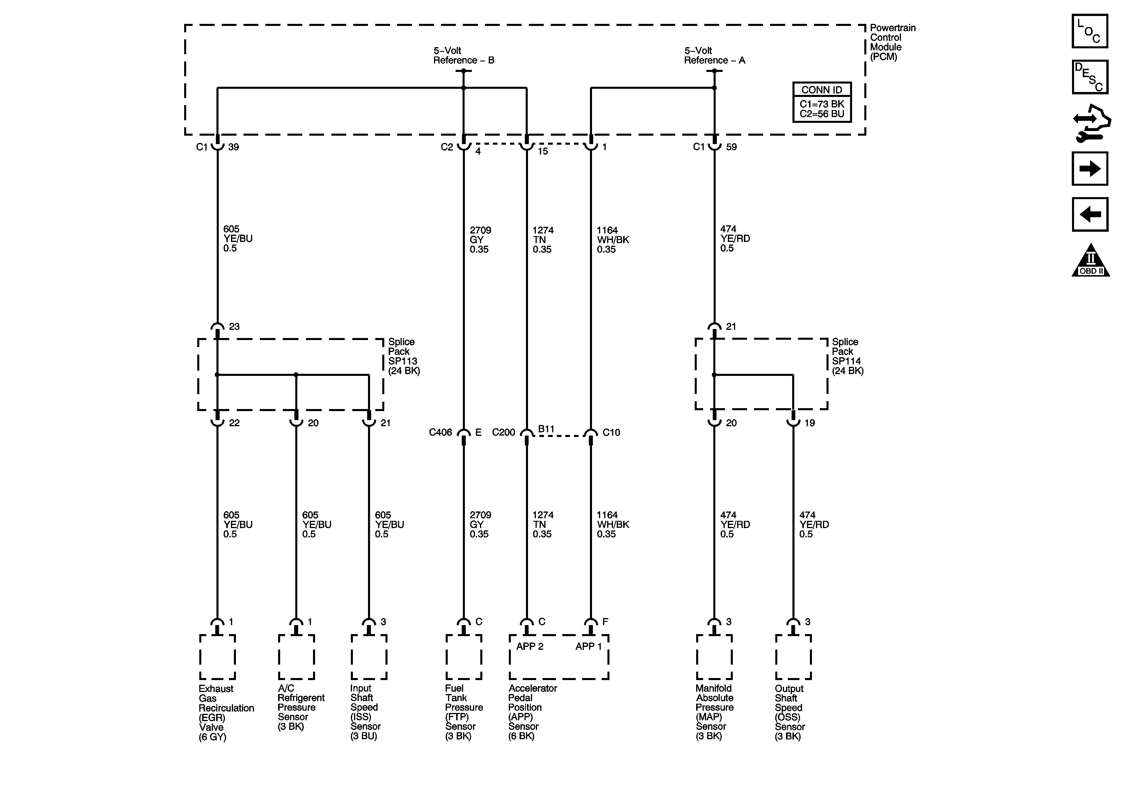
Figure 2:

5-Volt References


Object Number: 1583996  Size: FS
Master Electrical Component List
Powertrain Control Module Description
Control Module References
Low References
PCM Power, Ground, Communication and the MIL
Engine Controls Schematic Icons
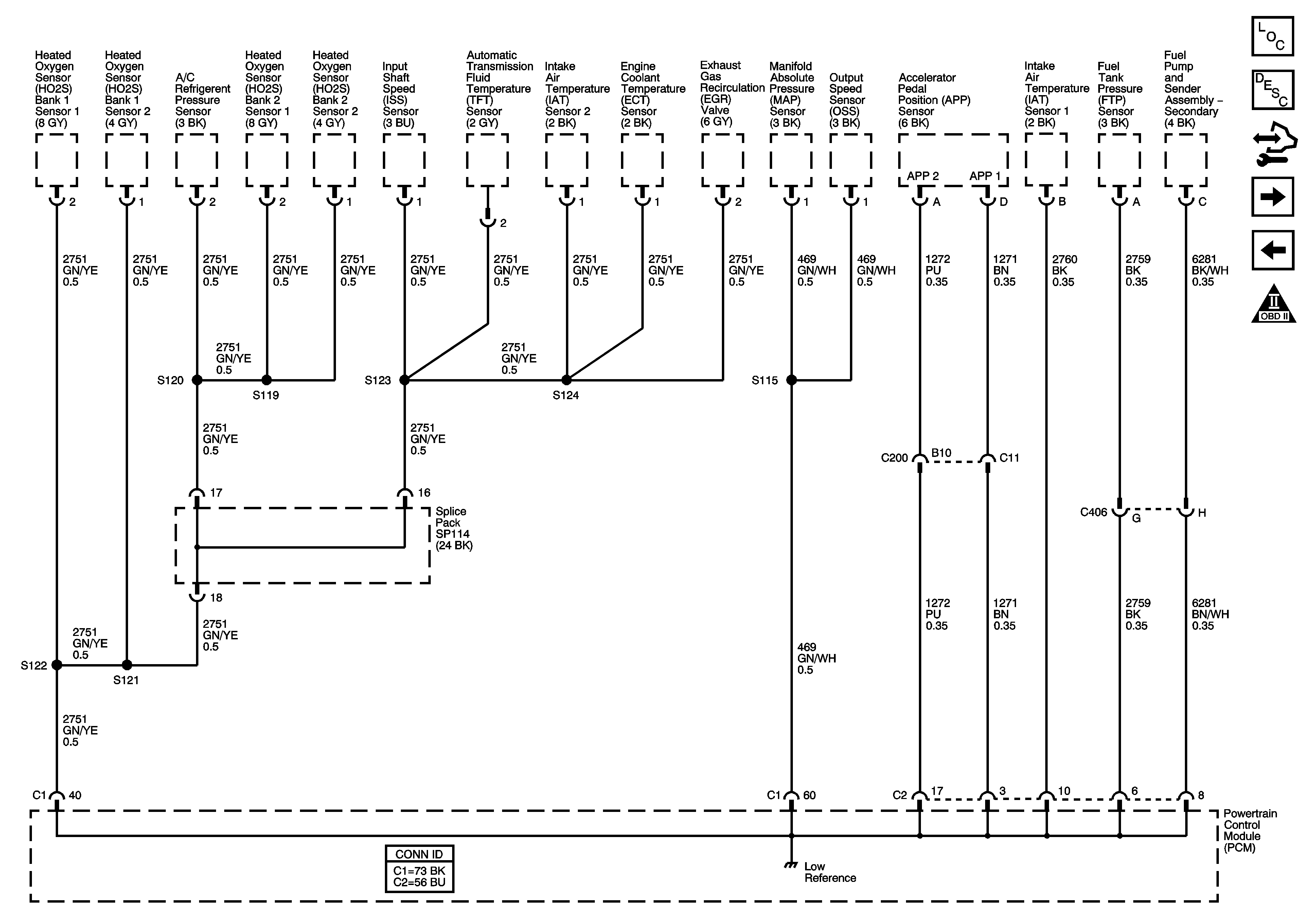
Figure 3:

Low References


Object Number: 1583997  Size: FS
Master Electrical Component List
Powertrain Control Module Description
Control Module References
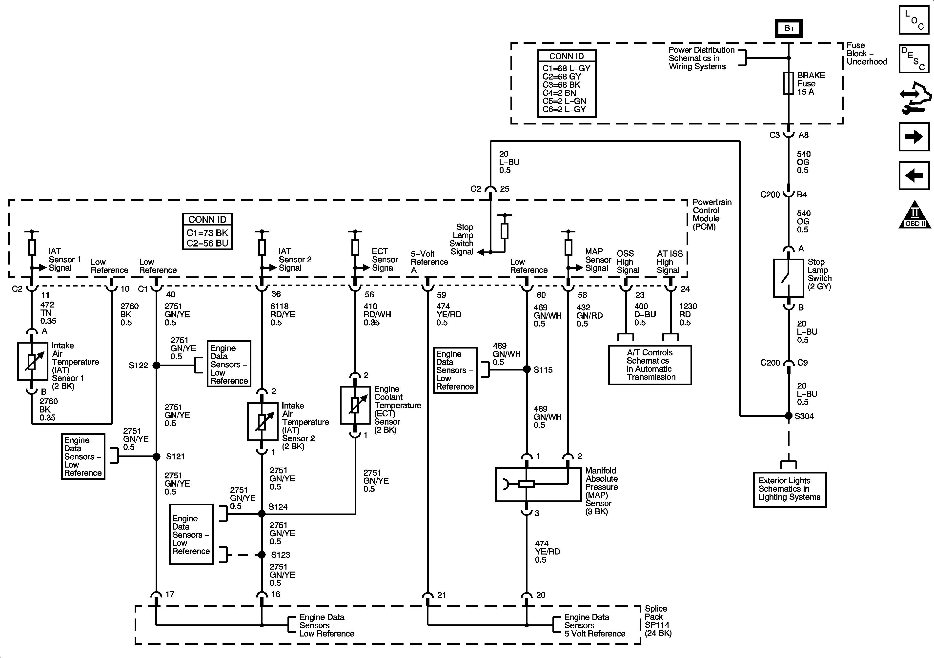
Engine Data Sensors - Pressure, Temperature and the Stop Lamp Switch
5-Volt References
Engine Controls Schematic Icons
Figure 4:

Engine Data Sensors - Pressure, Temperature and the Stop Lamp Switch


Object Number: 1583998  Size: FS
Master Electrical Component List
Powertrain Control Module Description
Control Module References
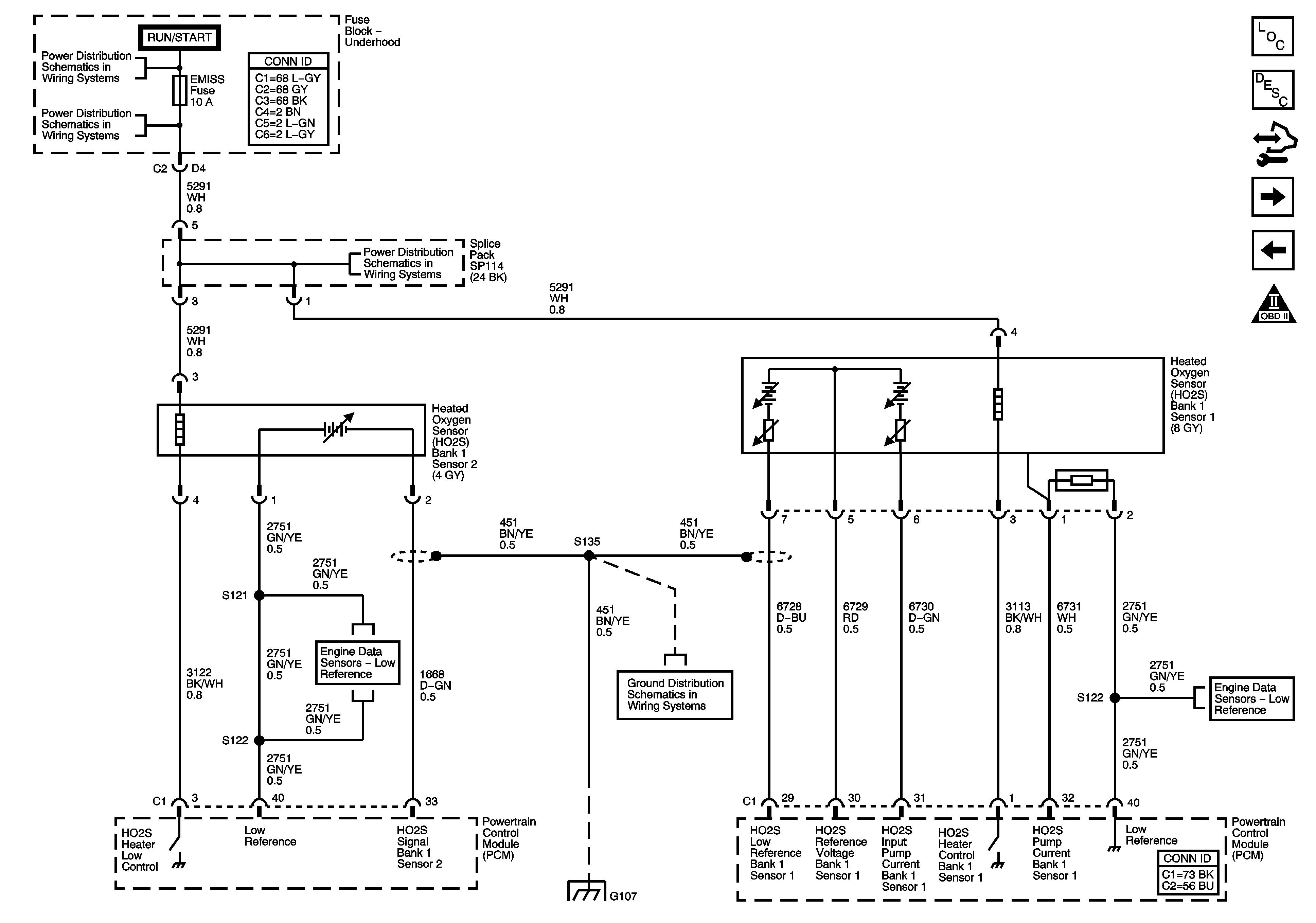
Engine Data Sensors - Bank 1 Oxygen Sensors
Low References
Engine Controls Schematic Icons
Low References
Low References
Low References
Low References
Low References
B+ Bussing and the EPS Fuse
PNP Switch Signals, OSS, ISS, IPC Indicators and PCM Communication
5-Volt References
Stop Lamps
Figure 5:

Engine Data Sensors - Bank 1 Oxygen Sensors


Object Number: 1584000  Size: FS
Master Electrical Component List
Powertrain Control Module Description
Control Module References
Engine Data Sensors - Bank 2 Oxygen Sensors
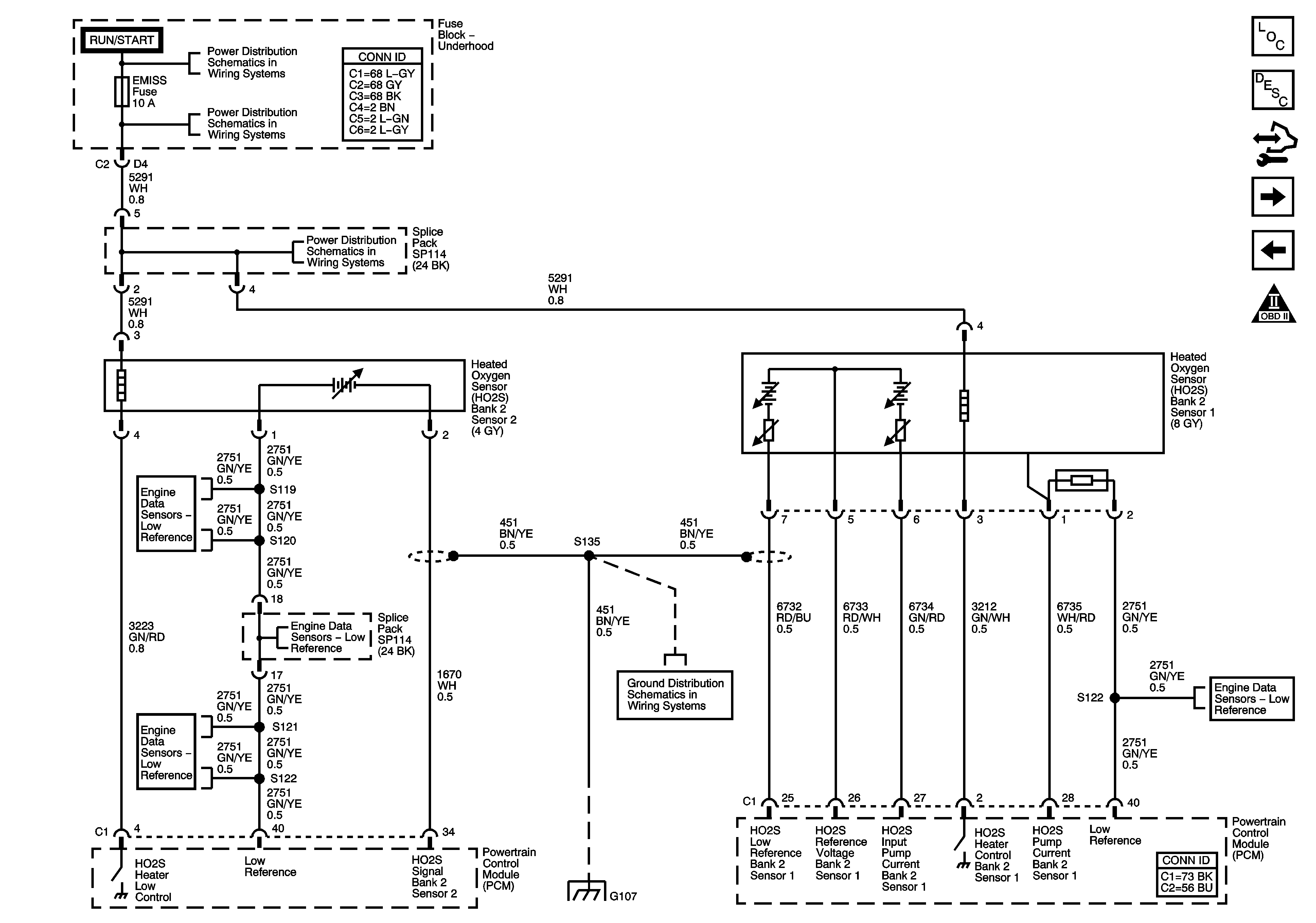
Engine Data Sensors - Pressure, Temperature and the Stop Lamp Switch
Engine Controls Schematic Icons
IGN/INJ Fuse, EMISS Fuse and the ETC Fuse - L61
EMISS Fuse and the ETC Fuse - L66
G107 and G109 - L66
G107 and G109 - L66
Low References
Figure 6:

Engine Data Sensors - Bank 2 Oxygen Sensors


Object Number: 1584002  Size: FS
Master Electrical Component List
Powertrain Control Module Description
Control Module References
Engine Data Sensors - Throttle Actuator Controls
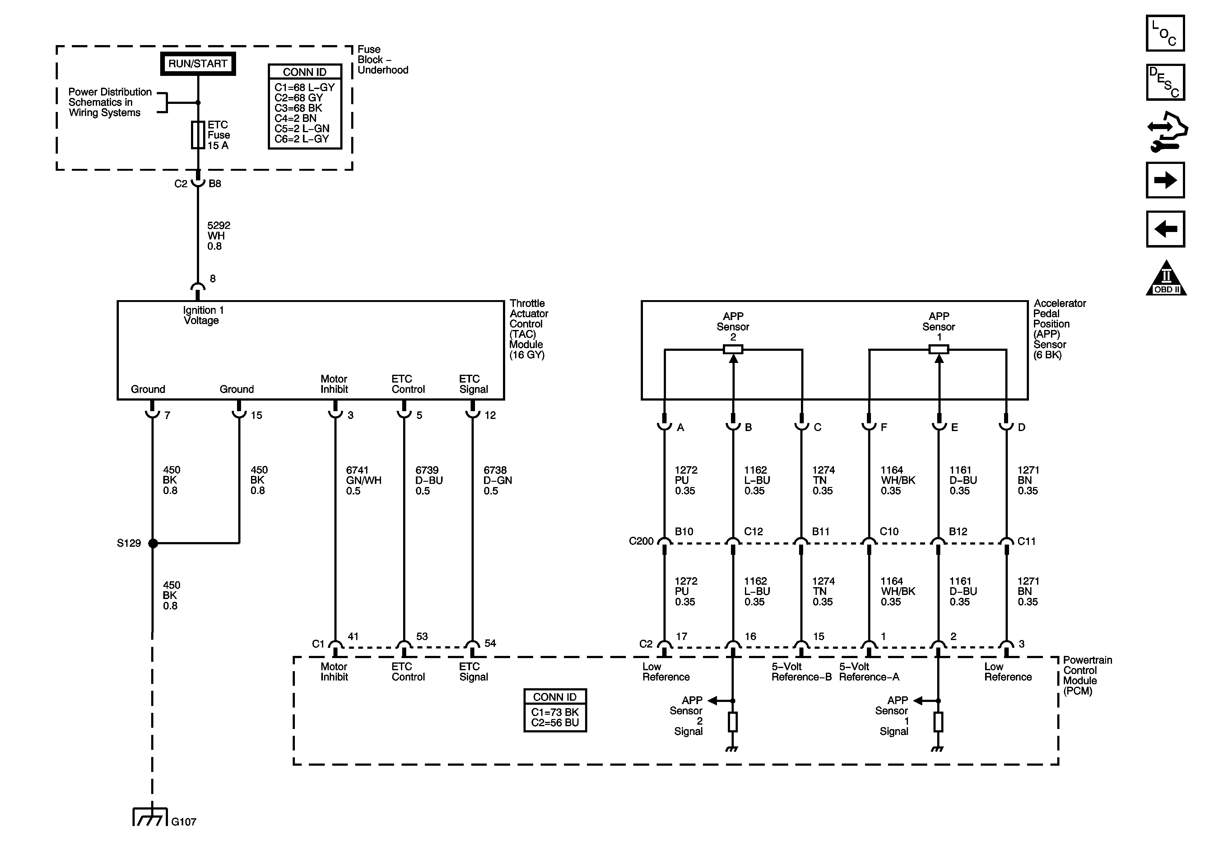
Engine Data Sensors - Bank 1 Oxygen Sensors
Engine Controls Schematic Icons
IGN/INJ Fuse, EMISS Fuse and the ETC Fuse - L61
EMISS Fuse and the ETC Fuse - L66
G107 and G109 - L66
G107 and G109 - L66
EMISS Fuse and the ETC Fuse - L66
Low References
Low References
Low References
Figure 7:

Engine Data Sensors - Throttle Actuator Controls


Object Number: 1584003  Size: FS
Master Electrical Component List
Throttle Actuator Control (TAC) System Description
Control Module References
Ignition Controls - Ignition Modules
Engine Data Sensors - Bank 2 Oxygen Sensors
Engine Controls Schematic Icons
B+ Bussing and the EPS Fuse
G107 and G109 - L66
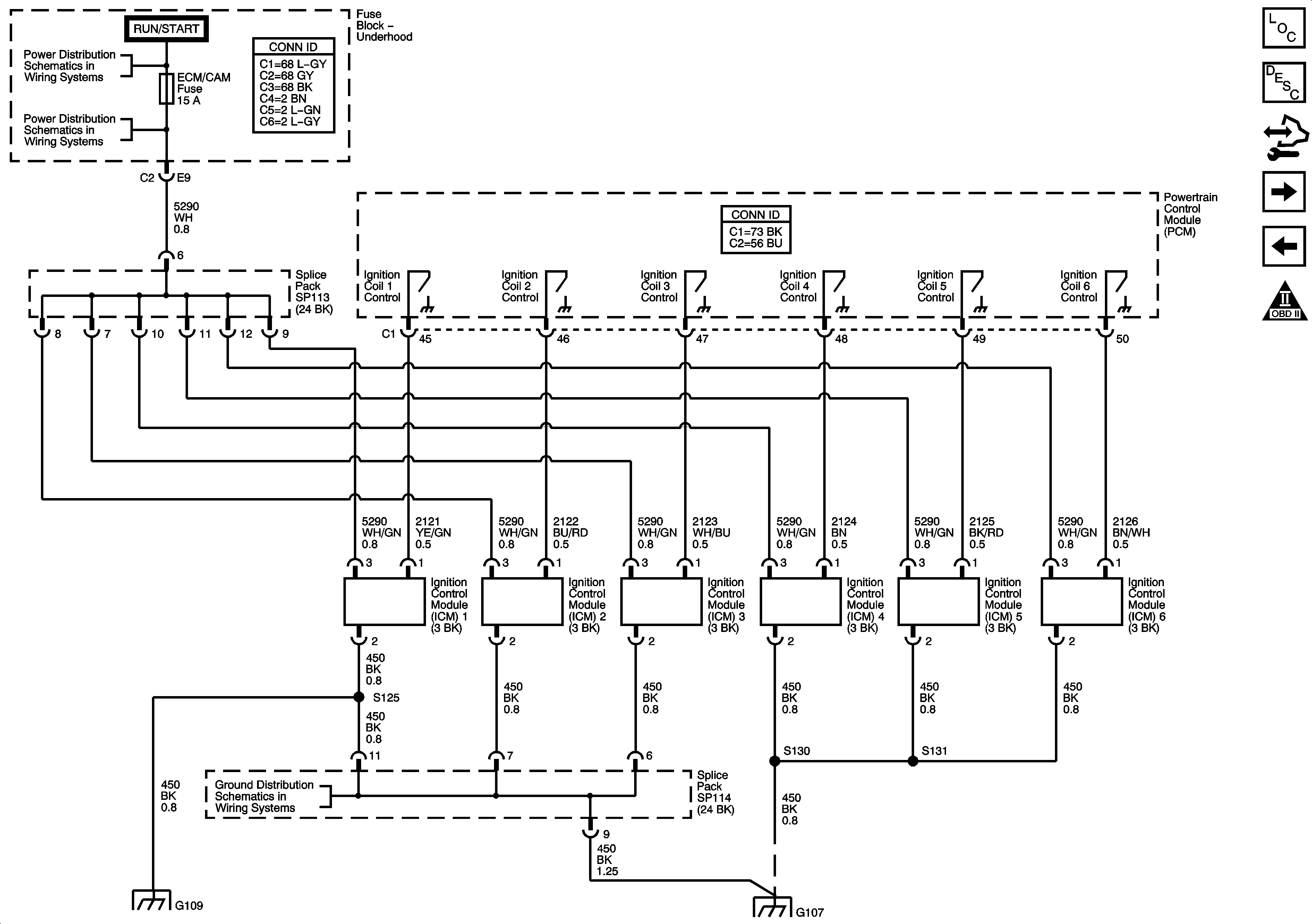
Figure 8:

Ignition Controls - Ignition Modules


Object Number: 1584005  Size: FS
Master Electrical Component List
Throttle Actuator Control (TAC) System Description
Control Module References
Engine Data Sensors - KS, CKP and CMP Sensors
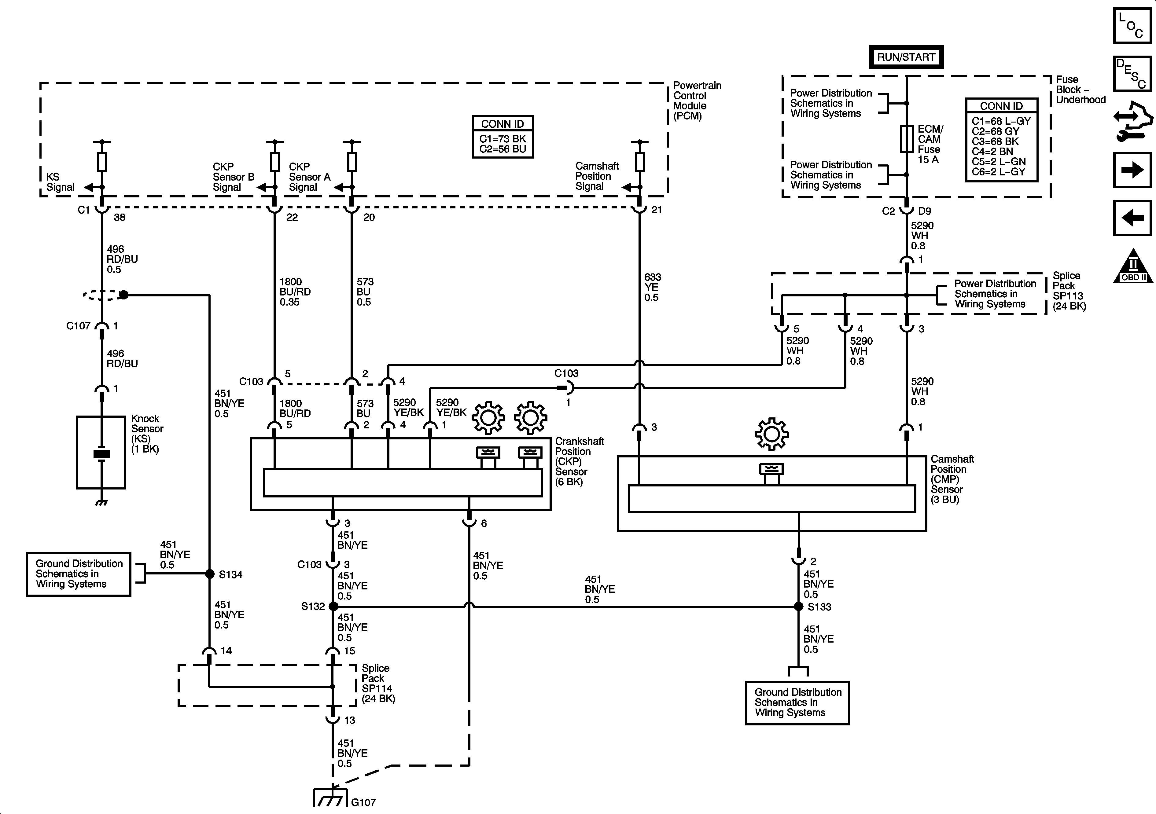
Engine Data Sensors - Throttle Actuator Controls
Engine Controls Schematic Icons
B+ Bussing and the EPS Fuse
ECM/CAM Fuse - L66
G107 and G109 - L66
G107 and G109 - L66
Figure 9:

Engine Data Sensors - KS, CKP and CMP Sensors


Object Number: 1584009  Size: FS
Master Electrical Component List
Electronic Ignition (EI) System Description
Control Module References
Fuel Controls - Fuel Pump, Injectors, Rocker Arm Solenoid and Rocker Arm Switch
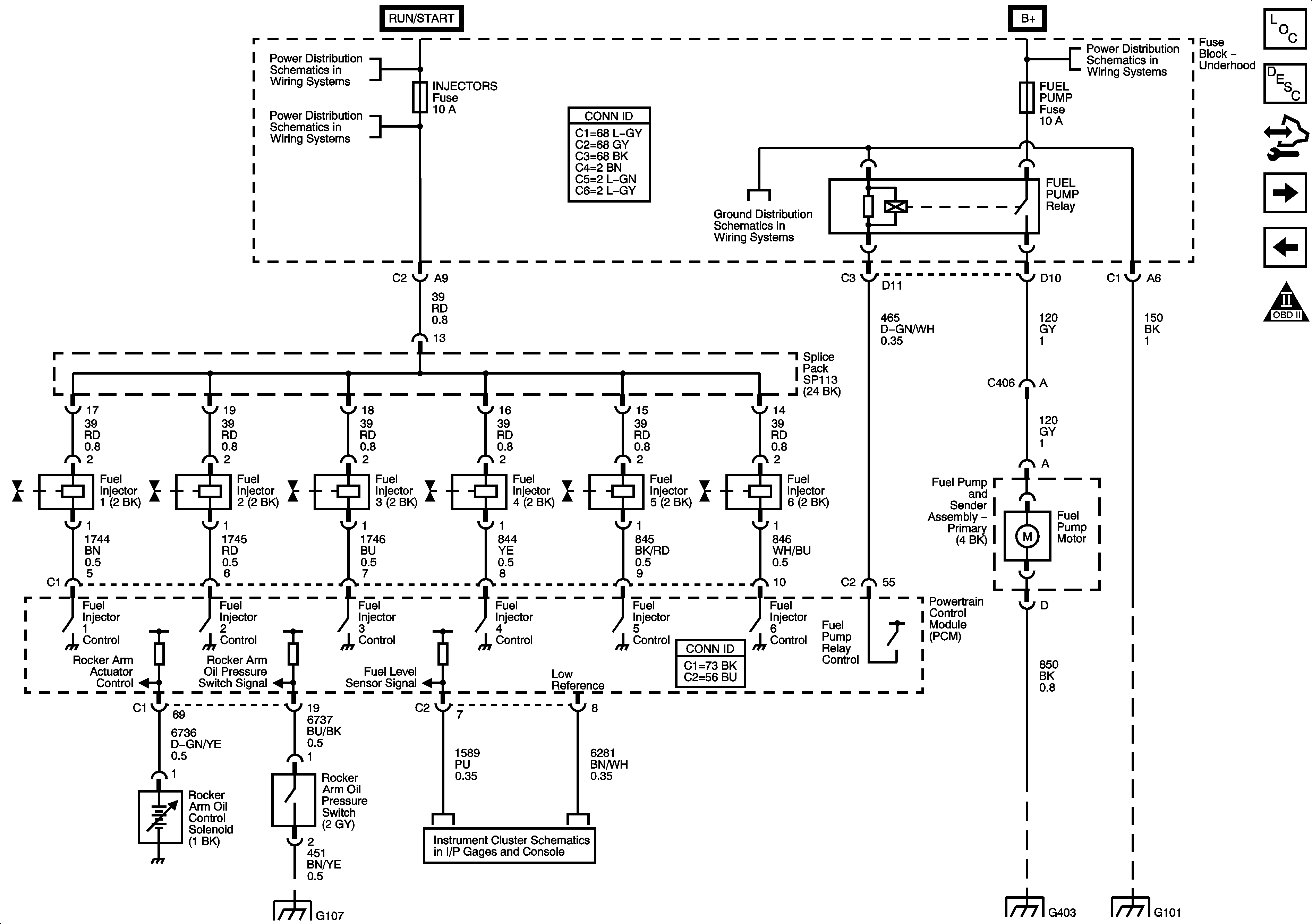
Ignition Controls - Ignition Modules
Engine Controls Schematic Icons
G107 and G109 - L66
G107 and G109 - L66
G107 and G109 - L66
B+ Bussing and the EPS Fuse
ECM/CAM Fuse - L66
ECM/CAM Fuse - L66
Figure 10:

Fuel Controls - Fuel Pump, Injectors, Rocker Arm Solenoid and Rocker Arm Switch


Object Number: 1584010  Size: FS
Master Electrical Component List
Fuel System Description
Control Module References
EVAP Controls
Engine Data Sensors - KS, CKP and CMP Sensors
Engine Controls Schematic Icons
IGN Fuse and the Ignition Switch Circuits
BACKUP Fuse, PWR TRAIN Fuse, 10A ABS Fuse and the INJECTORS (L66) Fuse
G107 and G109 - L66
Gages
G101
G401 and G403
G101
B+ Bussing and the EPS Fuse
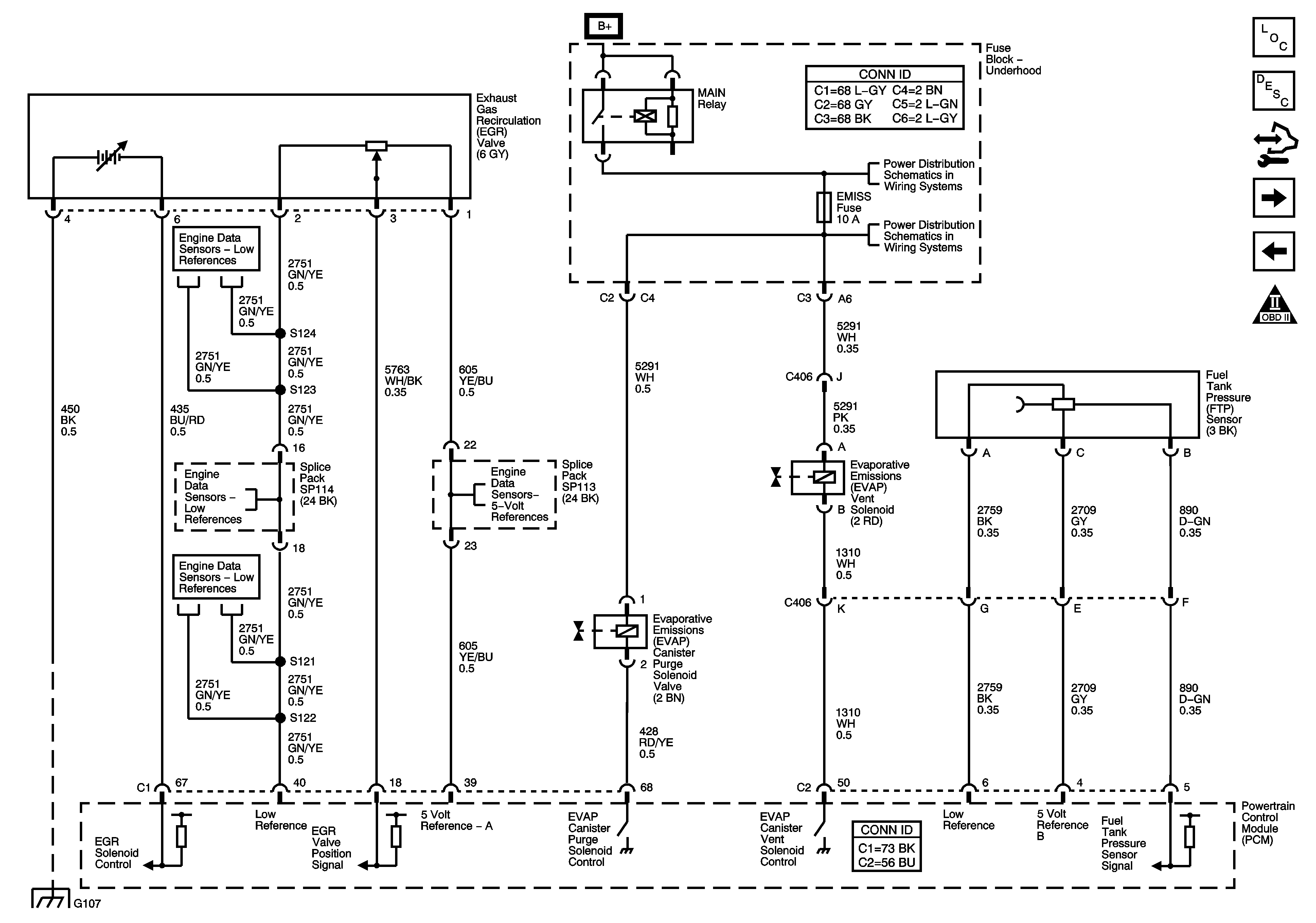
Figure 11:

Fuel Controls - EVAP Controls


Object Number: 1608189  Size: FS
Master Electrical Component List
Evaporative Emission Control System Description
Control Module References
Controlled/Monitored Subsystem References
Fuel Controls - Fuel Pump, Injectors, Rocker Arm Solenoid and Rocker Arm Switch
Engine Controls Schematic Icons
Low References
Low References
Low References
G107 and G109 - L66
B+ Bussing and the EPS Fuse
EMISS Fuse and the ETC Fuse - L66
5-Volt References
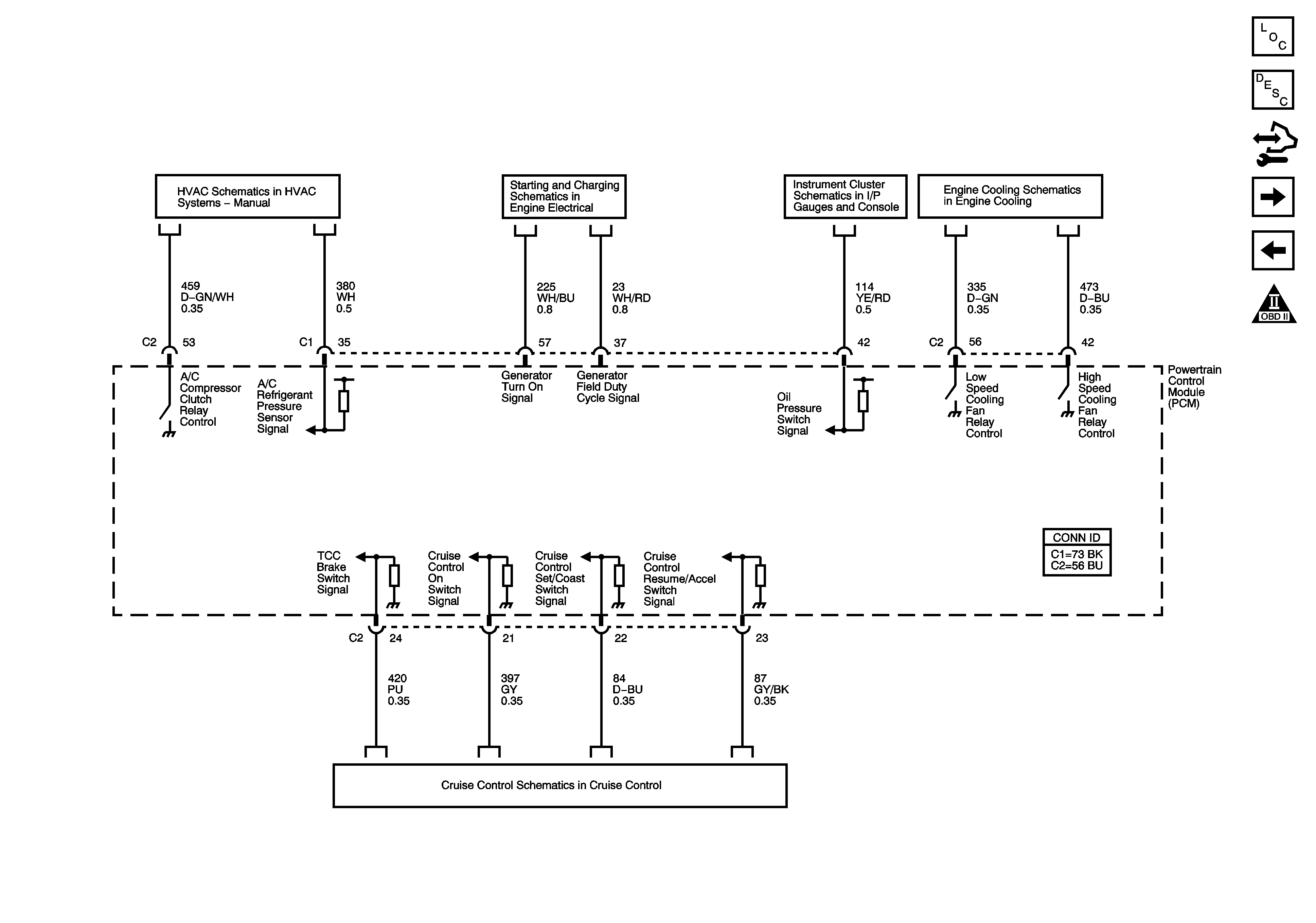
Figure 12:

Controlled/Monitored Subsystem References


Object Number: 1584013  Size: FS
Master Electrical Component List
Powertrain Control Module Description
Control Module References
Transmission Controls References
EVAP Controls
Engine Controls Schematic Icons
Compressor and Pressure Sensor Signals
Charging and Indicators
Indicators and Serial Data
Engine Cooling Schematic (L66)
Cruise Control Schematic
Figure 13:

Transmission Controls References


Object Number: 1584014  Size: FS
Master Electrical Component List
Powertrain Control Module Description
Control Module References
Controlled/Monitored Subsystem References
Engine Controls Schematic Icons
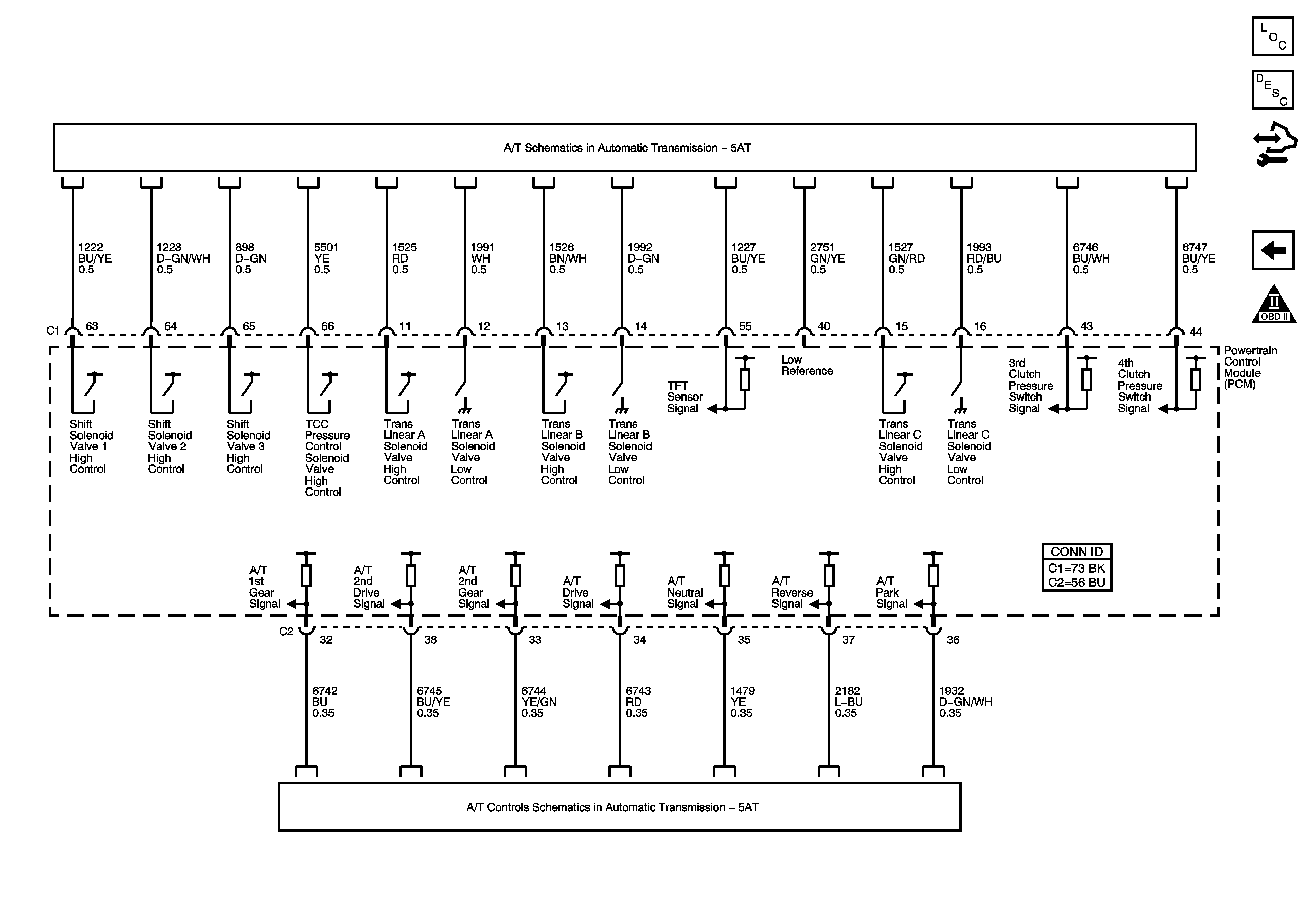
Solenoid and Switch Controls
PNP Switch Signals, OSS, ISS, IPC Indicators and PCM Communication