For 1990-2009 cars only
Exhaust Manifold Replacement Right Side
Removal Procedure
- Remove the oil level indicator and tube. Refer to Oil Level Indicator and Tube Replacement .
- Raise and suitably support the vehicle. Refer to Lifting and Jacking the Vehicle in General Information.
- Remove the right exhaust manifold pipe nuts.
- Lower the vehicle.
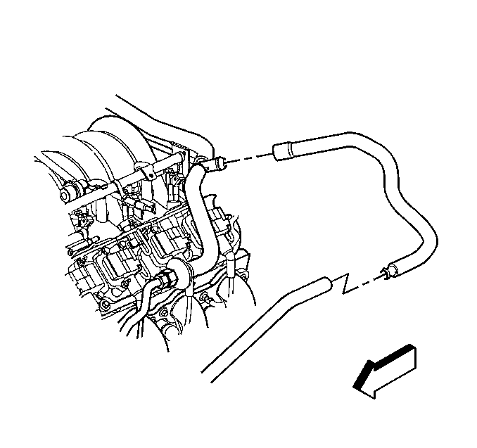
- Disconnect the secondary air injection (AIR) pump hose from the check valve hose.
- Remove the AIR check valve hose clamps and hose.
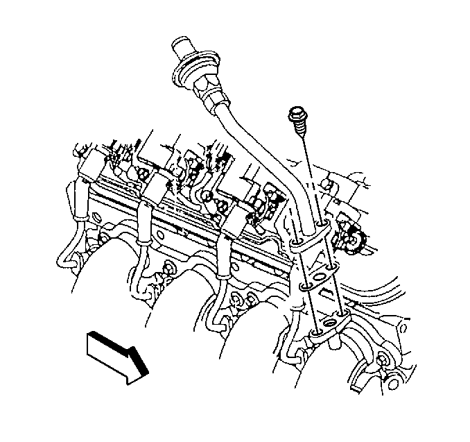
- Remove the AIR pipe (with check valve), bolts and gasket from the right exhaust manifold.
- Remove the spark plug wires from the ignition coils.
- Remove the spark plug wires from the spark plugs.
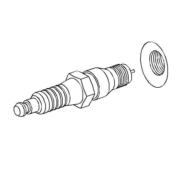
- Remove the spark plugs.
- Remove the valve rocker arm cover. Refer to Valve Rocker Arm Cover Replacement .
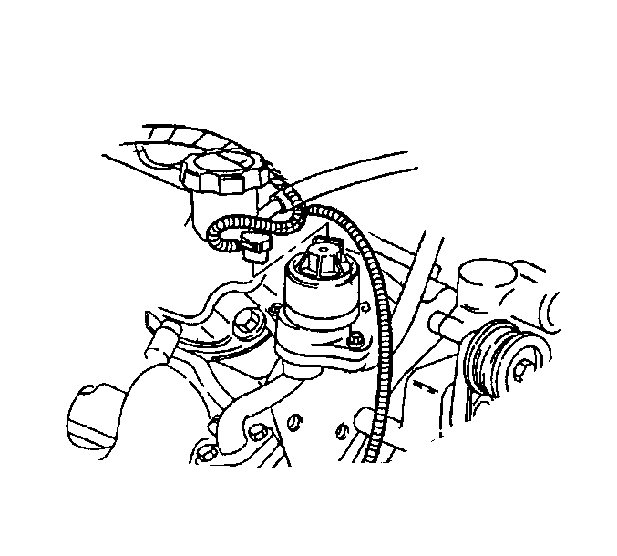
- Disconnect the exhaust gas recirculation (EGR) valve electrical connector.
- Remove the exhaust manifold. Refer to Exhaust Manifold Removal .



Installation Procedure
- Install the exhaust manifold. Refer to Exhaust Manifold Installation .
- Connect the EGR valve electrical connector.
- Install the valve rocker arm cover. Refer to Valve Rocker Arm Cover Replacement .
- Install the spark plugs.
- Install the spark plug wires to the spark plugs.
- Install the spark plug wires to the ignition coils.
- Install the AIR pipe (with check valve), bolts and gasket to the right exhaust manifold.
- Install the AIR check valve hose and clamps.
- Connect the AIR pump hose to the check valve hose.
- Raise and suitably support the vehicle. Refer to Lifting and Jacking the Vehicle in General Information.
- Install the right exhaust manifold pipe nuts.
- Install the oil level indicator and tube. Refer to Oil Level Indicator and Tube Replacement .
- Lower the vehicle.
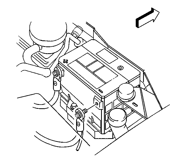
- Connect the negative battery cable. Refer to Battery Negative Cable Disconnection and Connection in Engine Electrical.


Tighten
Tighten the spark plugs to 15 N·m (11 lb ft).


Tighten
Tighten the AIR pipe to exhaust manifold bolts to 20 N·m
(15 lb ft).


Tighten
Tighten the right exhaust manifold pipe nuts to 35 N·m
(26 lb ft).
Exhaust Manifold Replacement Left Side
Removal Procedure
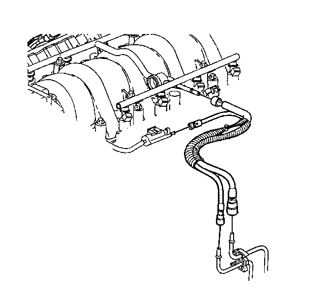
- Relieve the fuel system pressure. Refer to Fuel Pressure Relief Procedure in Engine Controls - 5.7L.
- Disconnect the fuel line from the fuel rail.
- Disconnect the vapor line from the fuel vapor purge valve.
- Remove the fuel rail. Refer to Fuel Rail and Injectors Removal .
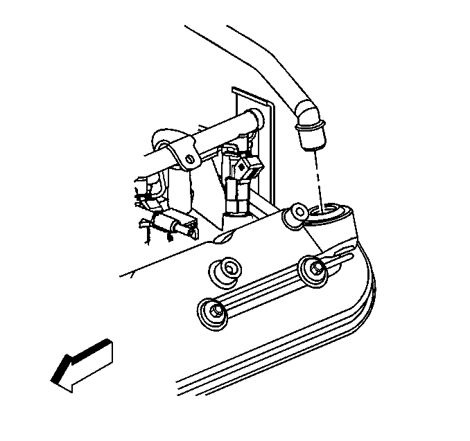
- Remove the positive crankcase ventilation (PCV) valve pipe from the rocker cover.
- Remove the spark plug wires from the ignition coils.
- Remove the spark plug wires from the spark plugs.
- Remove the spark plugs.
- Disconnect the secondary air injection (AIR) pump hose from the check valve hose.
- Remove the AIR check valve hose clamps and hose.
- Remove the AIR pipe (with check valve), bolts and gasket from the left exhaust manifold.
- Remove the left side exhaust manifold bolts.
- Raise and suitably support the vehicle. Refer to Lifting and Jacking the Vehicle in General Information.
- Disconnect the oxygen sensor electrical connector.
- Remove the oxygen sensor from the exhaust manifold.
- Remove the exhaust manifold pipe nuts.
- Remove the catalytic converter nuts.
- Remove the exhaust manifold. Refer to Exhaust Manifold Removal .


Installation Procedure
- Install the exhaust manifold. Refer to Exhaust Manifold Installation .
- Install the catalytic converter nuts.
- Install the exhaust manifold pipe nuts.
- Install the oxygen sensor to the exhaust manifold.
- Connect the oxygen sensor electrical connector.
- Lower the vehicle.
- Install the AIR pipe (with check valve), bolts and gasket to the left exhaust manifold.
- Install the AIR check valve hose and clamps.
- Connect the AIR pump hose to the check valve hose.
- Install the spark plugs.
- Install the spark plug wires to the spark plugs.
- Install the spark plug wires to the ignition coils.
- Install the PCV valve pipe to the rocker cover.
- Install the fuel rail. Refer to Fuel Rail and Injectors Installation
- Connect the fuel line to the fuel rail.
- Connect the vapor line to the fuel vapor purge valve.

Tighten
Tighten the catalytic converter nuts to 25 N·m (18 lb ft).

Tighten
Tighten the exhaust manifold pipe nuts to 35 N·m (26 lb ft).

Tighten
Tighten the oxygen sensor to 42 N·m (31 lb ft).

Tighten
Tighten the AIR pipe bolts 20 N·m (15 lb ft).


Tighten
Tighten the spark plugs to 15 N·m (11 lb ft).


