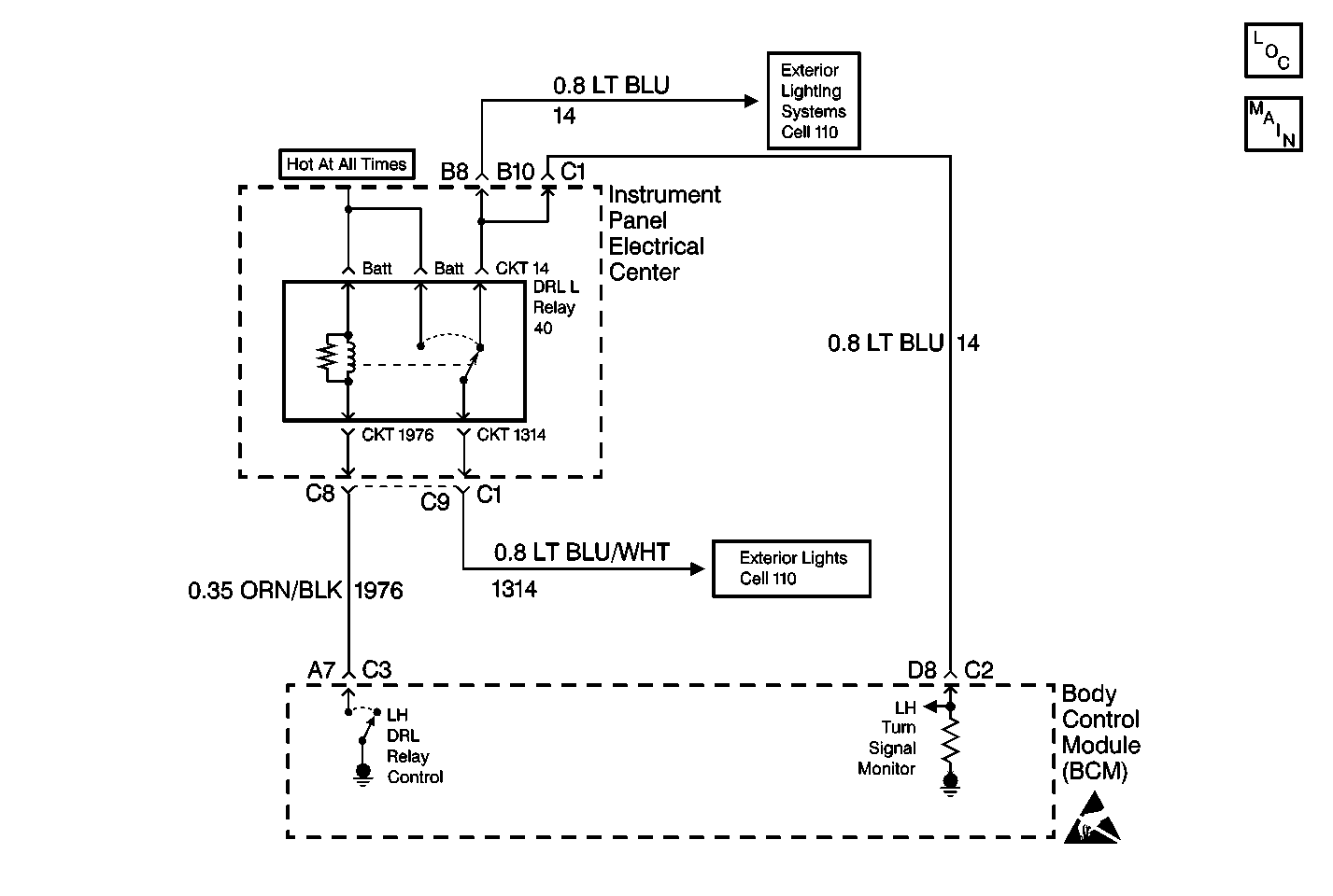
Circuit Description
The BCM monitors the LF turn signal circuit in order to determine the status of the turn signal switch. If the BCM detects an oscillating voltage on CKT 14, the BCM interprets this as a LF turn signal ON request from the turn signal switch. The BCM will stop energizing the LH DRL relay, which will disable the LF turn signal lamp (which is ON for the DRL), thus allowing the LF turn signal to flash. If the BCM does not detect an oscillating voltage on CKT 14, the BCM interprets this as the LF turn signal being OFF. The BCM will then energize the LH DRL relay and continue normal DRL operation. The BCM monitors the LF turn signal CKT 14 and determines how long voltage is applied. If the voltage is applied for longer than expected, a malfunction is present and a DTC will set.
Conditions for Setting the DTC
| • | The BCM detects continuous battery voltage on the LF turn signal monitor circuit. |
| • | The condition must be present for longer than 5 seconds. |
Action Taken When the DTC Sets
| • | Stores a DTC B2583 in the BCM memory. |
| • | No driver warning message will be displayed for this DTC. |
Conditions for Clearing the DTC
| • | This DTC requires an ignition cycle in order to change from current to history. |
| • | The BCM no longer detects continuous battery voltage on the LF turn signal monitor circuit for longer than 5 seconds. |
| • | A history DTC will clear after 50 consecutive ignition cycles if the condition for the malfunction is no longer present. |
| • | Use the IPC clearing DTCs feature. |
| • | Use a scan tool. |
Diagnostic Aids
| • | The following conditions may cause an intermittent malfunction: |
| - | There is an intermittent short to voltage in CKT 14, CKT 16, or CKT 1314. |
| - | The turn signal switch or the hazard switch is internally shorted or is sticking. |
| • | The BCM needs to detect voltage oscillations on CKT 14 in order to de-energize the LF turn signal relay. If the BCM detects continuous voltage on CKT 14, the BCM interprets this as a short to voltage. The BCM will continue with normal DRL operation, and the LF turn signal will remain inoperative. |
| • | If the DTC is a history DTC, the problem may be intermittent. Perform the tests shown while moving related wiring and connectors. This can often cause the malfunction to occur. Refer to Intermittents and Poor Connections . |
Test Description
The numbers below refer to the step numbers on the diagnostic table:
-
This test will check if a DTC B2578 is stored in the BCM memory.
-
This test will determine if there is a short to voltage in CKT 14.
-
This test will determine if there is a short to voltage in CKT 1314.
-
This step tests for an internal DRL relay short.
-
This test determines if the short to voltage is located in the hazard warning switch.
-
This test determines if the short to voltage is located in the turn signal switch.
-
This test determines if the short to voltage is located in the I/P.
Step | Action | Value(s) | Yes | No | ||||||||||
|---|---|---|---|---|---|---|---|---|---|---|---|---|---|---|
1 | Were you sent here from the BCM Diagnostic System Check? | -- | ||||||||||||
Using a scan tool, check for BCM DTC B2578. Is DTC B2578 stored in the BCM memory? | -- | |||||||||||||
Is the test light ON? | -- | |||||||||||||
With a test light connected to ground, probe CKT 1314 at the I/P electrical center LH DRL relay terminal. Refer to Electrical Center Identification Views for relay circuit location. Is the test light ON? | -- | |||||||||||||
Check for continuity between the LH DRL relay terminals 4 and 5 (or 87 and 87A). Is there continuity? | -- | |||||||||||||
Is the test light ON? | -- | |||||||||||||
Is the test light ON? | -- | |||||||||||||
Is the test light ON? | -- | |||||||||||||
9 | Inspect for the following intermittent malfunctions:
Was a problem found and repaired? | -- | ||||||||||||
10 |
Does DTC B2583 set as current? | -- | System OK | |||||||||||
11 | Locate and repair the short to voltage in CKT 14. Is the circuit repair complete? | -- | -- | |||||||||||
12 | Locate and repair the short to voltage at the IPC connector terminal A15. Is the circuit repair complete? | -- | -- | |||||||||||
13 | Locate and repair the short to voltage in CKT 1314. Is the circuit repair complete? | -- | -- | |||||||||||
14 | Check for a short to voltage in CKT 16. Was a condition found and repaired? | -- | ||||||||||||
15 | Replace the turn signal switch. Refer to Turn Signal and Multifunction Switch Assembly in Steering Wheel and Column. Is the replacement complete? | -- | -- | |||||||||||
16 | Replace the hazard warning switch. Refer to Hazard Warning Switch Replacement in Lighting Systems. Is the repair complete? | -- | -- | |||||||||||
17 | Replace the LH DRL relay. Is the replacement complete? | -- | -- | |||||||||||
18 |
Is the replacement complete? | -- | -- | |||||||||||
19 |
Are all DTCs cleared? | -- | -- |
