For 1990-2009 cars only
Removal Procedure
- Disconnect the negative battery cable. Refer to Battery Negative Cable Disconnection and Connection.
- Remove the hood. Refer to Hood Replacement.
- Remove the intake manifold cover. Refer to Intake Manifold Cover Replacement.
- Remove the air cleaner assembly. Refer to Air Cleaner Assembly Replacement.
- Remove the engine mount struts. Refer to Engine Mount Strut Replacement.
- Remove the drive belt. Refer to Drive Belt Replacement.
- Drain the cooling system. Refer to Cooling System Draining and Filling.
- Drain the engine oil. Refer to Engine Oil and Oil Filter Replacement.
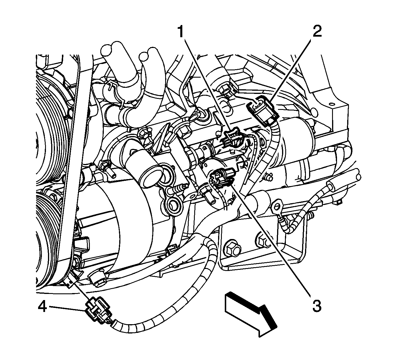
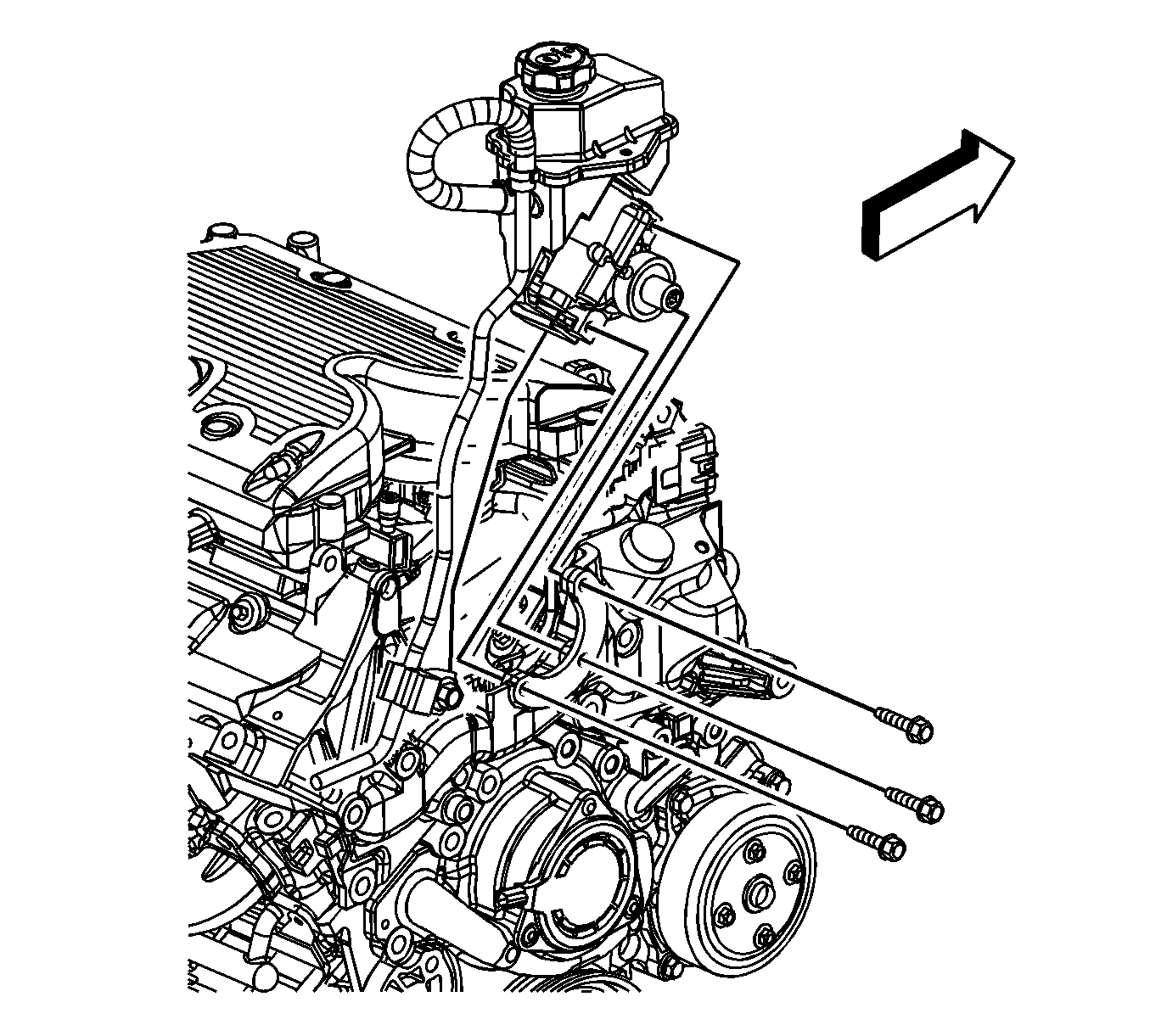
- Remove the oil pressure sensor heat shield nuts and shield.
- Disconnect the oil pressure sensor electrical connector (1).
- Disconnect the knock sensor electrical connector (2).
- Disconnect the starter motor electrical connector (3).
- Disconnect the air conditioning (A/C) compressor electrical connector (4).
- Disconnect the oil level sensor electrical connector.
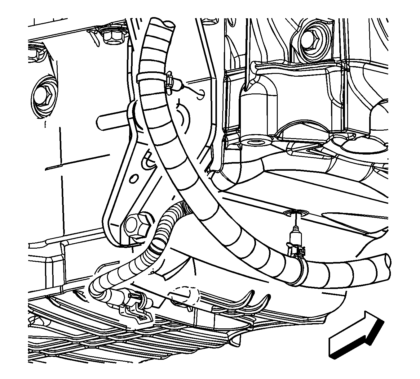
- Remove the engine harness clips from the transaxle brace and the oil pan.
- Lower the vehicle.
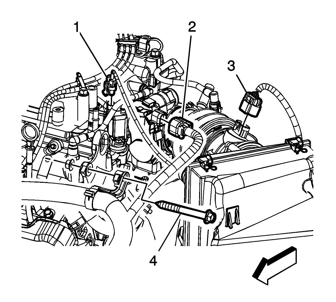
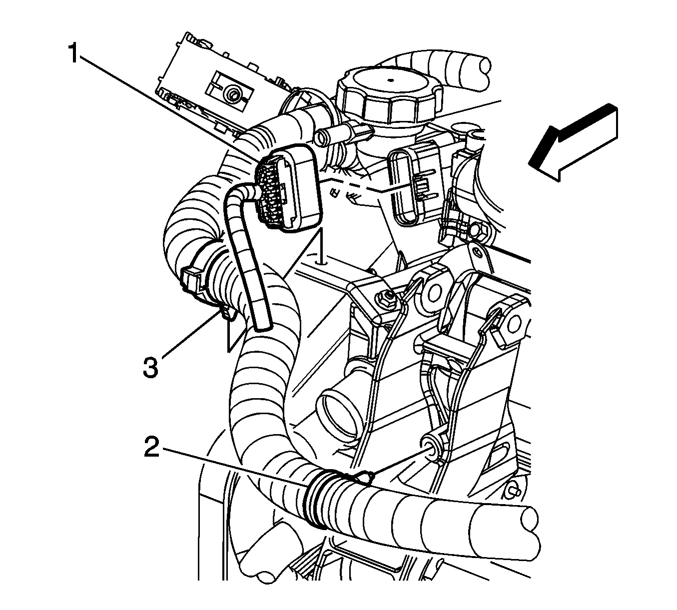
- Disconnect the evaporative emission (EVAP) canister purge solenoid electrical connector (1).
- Disconnect the electronic throttle control (ETC) electrical connector (2).
- Disconnect the manifold absolute pressure (MAP) sensor electrical connector (1).
- Reposition the generator terminal boot (2).
- Remove the generator terminal nut (5).
- Remove the generator terminal (4) from the stud.
- Disconnect the generator electrical connector (3).
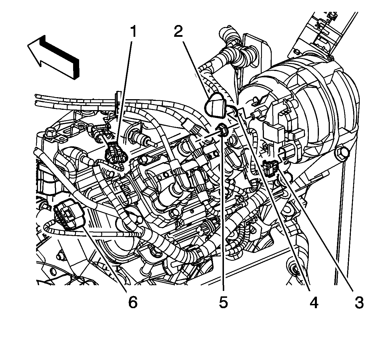
- Disconnect the ignition coil electrical connector (6).
- Disconnect the fuel injector inline (1) electrical connector.
- Remove the engine harness clips (2, 3) from the brackets.
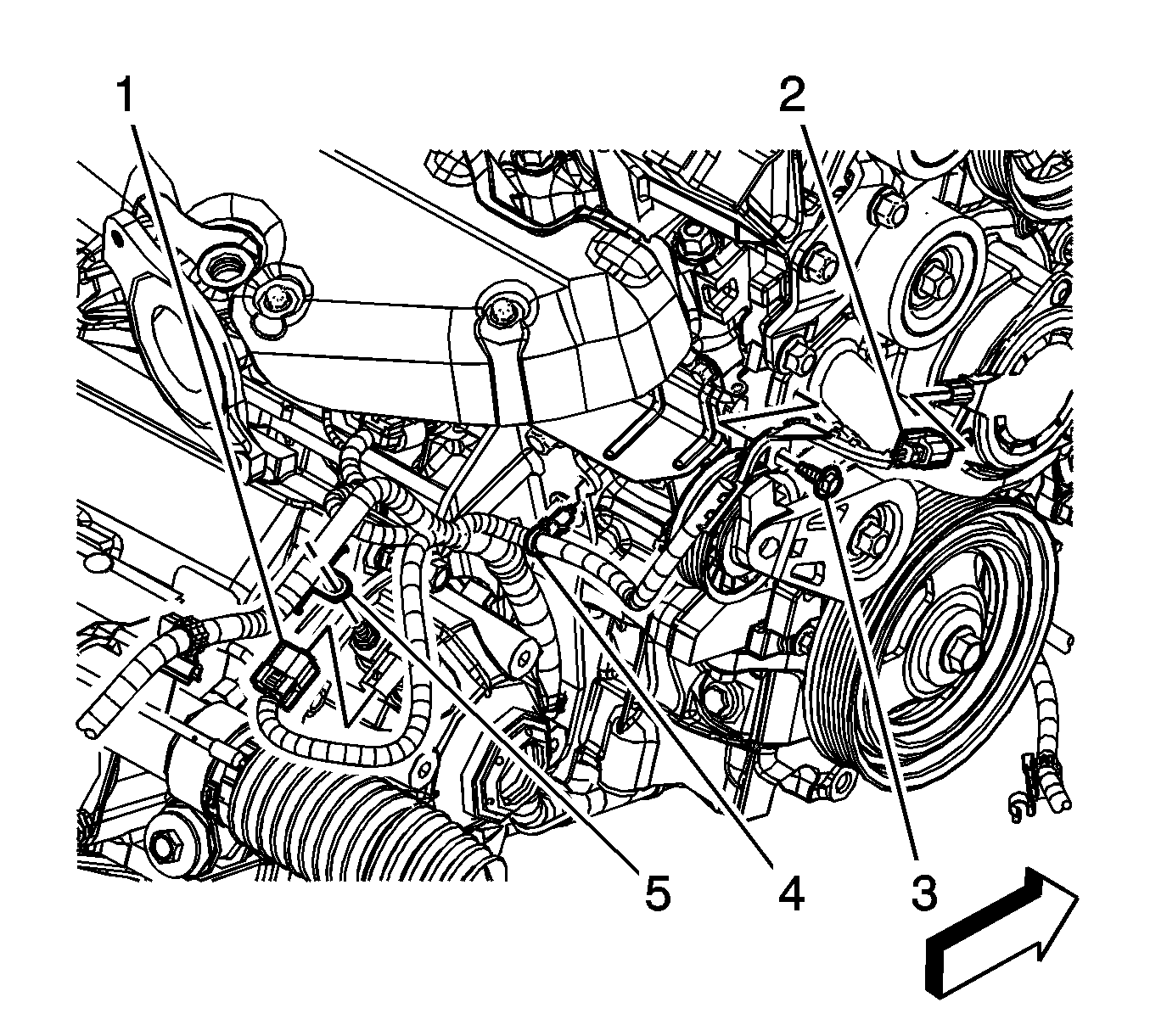
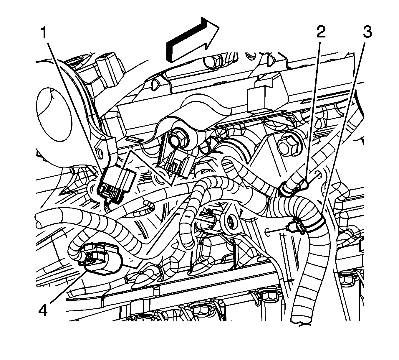
- Disconnect the camshaft phasor sensor electrical connector (2).
- Remove the engine harness clip bolt (3).
- Remove the engine harness clip (4) from the transaxle bracket.
- Remove the connector position assurance (CPA) retainer (3).
- Disconnect the rear upper heated oxygen sensor (HO2S) electrical connector (2).
- Disconnect the knock sensor electrical connector (1).
- Disconnect the crankshaft position (CKP) sensor electrical connector (4).
- Remove the engine harness clips (2, 3) from the transaxle brace.
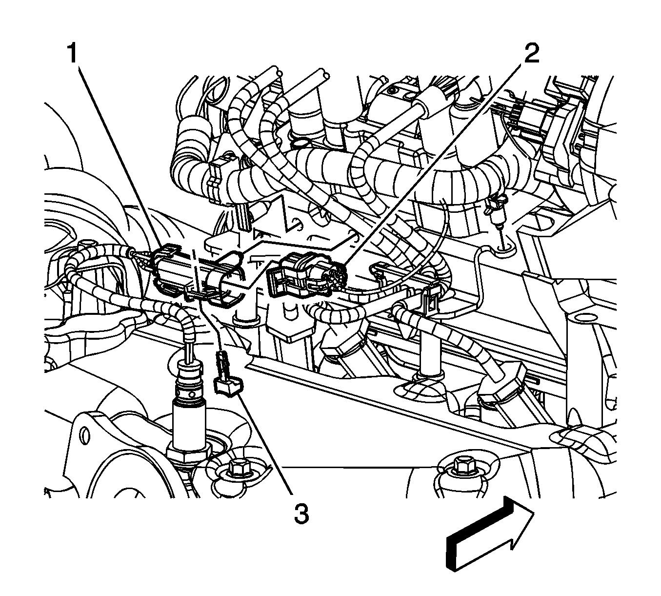
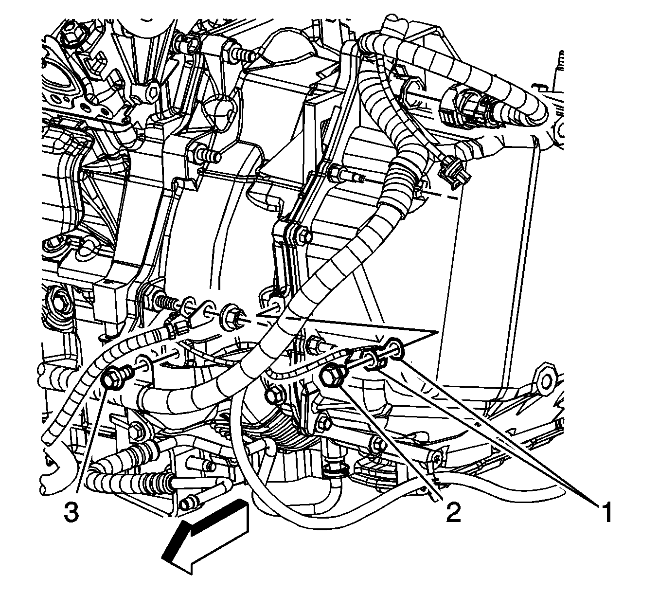
- Remove the engine harness ground bolt (2).
- Remove the engine harness ground terminals (1) from the transmission.
- Remove the engine harness clip bolt (3) from the transmission.
- Reposition all branches of the engine harness out of the way.
- Remove the catalytic converter. Refer to Catalytic Converter Replacement.
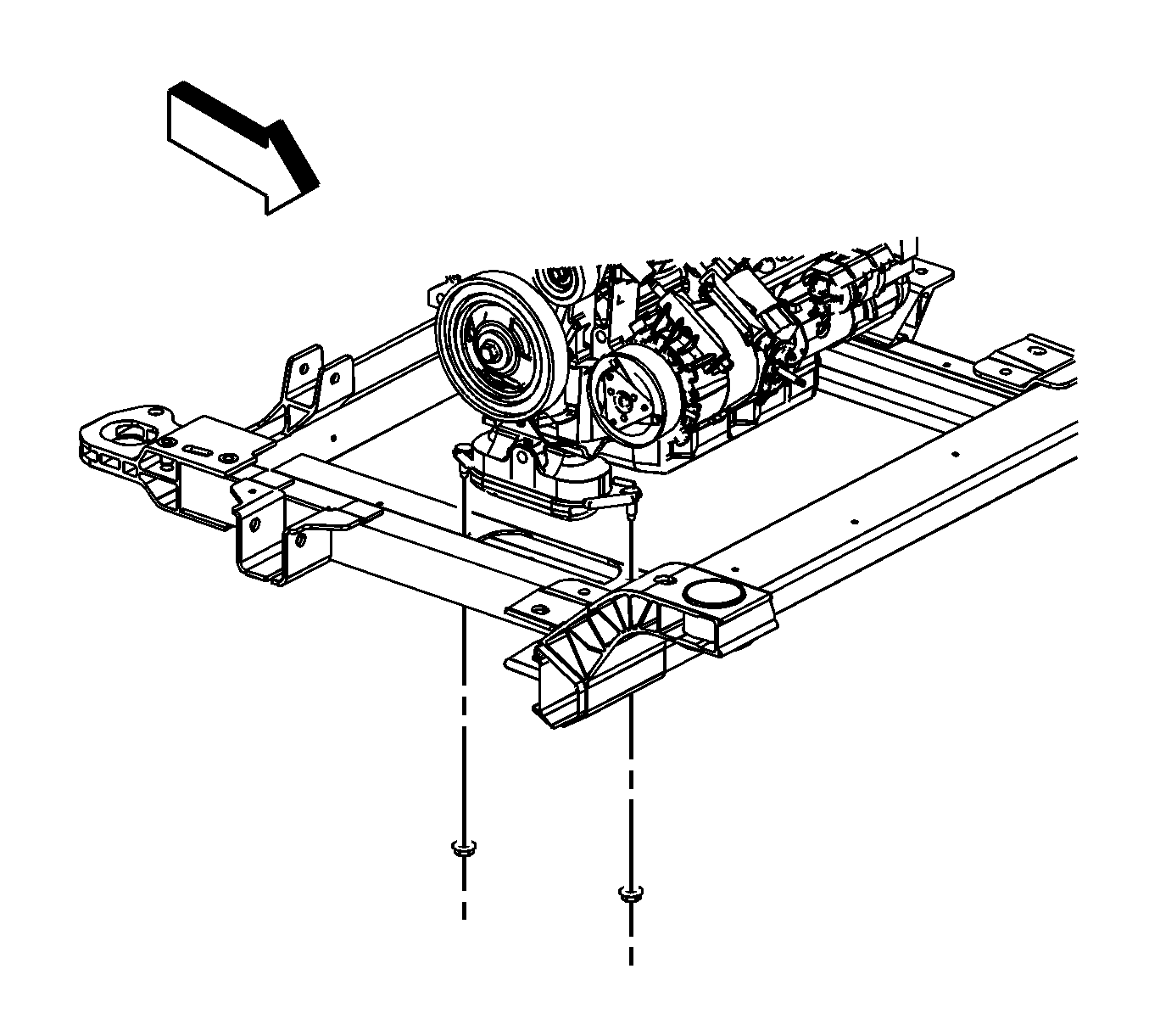
- Remove the engine mount lower nuts.
- Remove the torque converter cover. Refer to Torque Converter Cover Replacement.
- Remove the starter motor. Refer to Starter Motor Replacement.
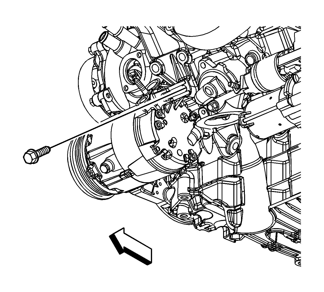
- Remove the torque converter bolts.
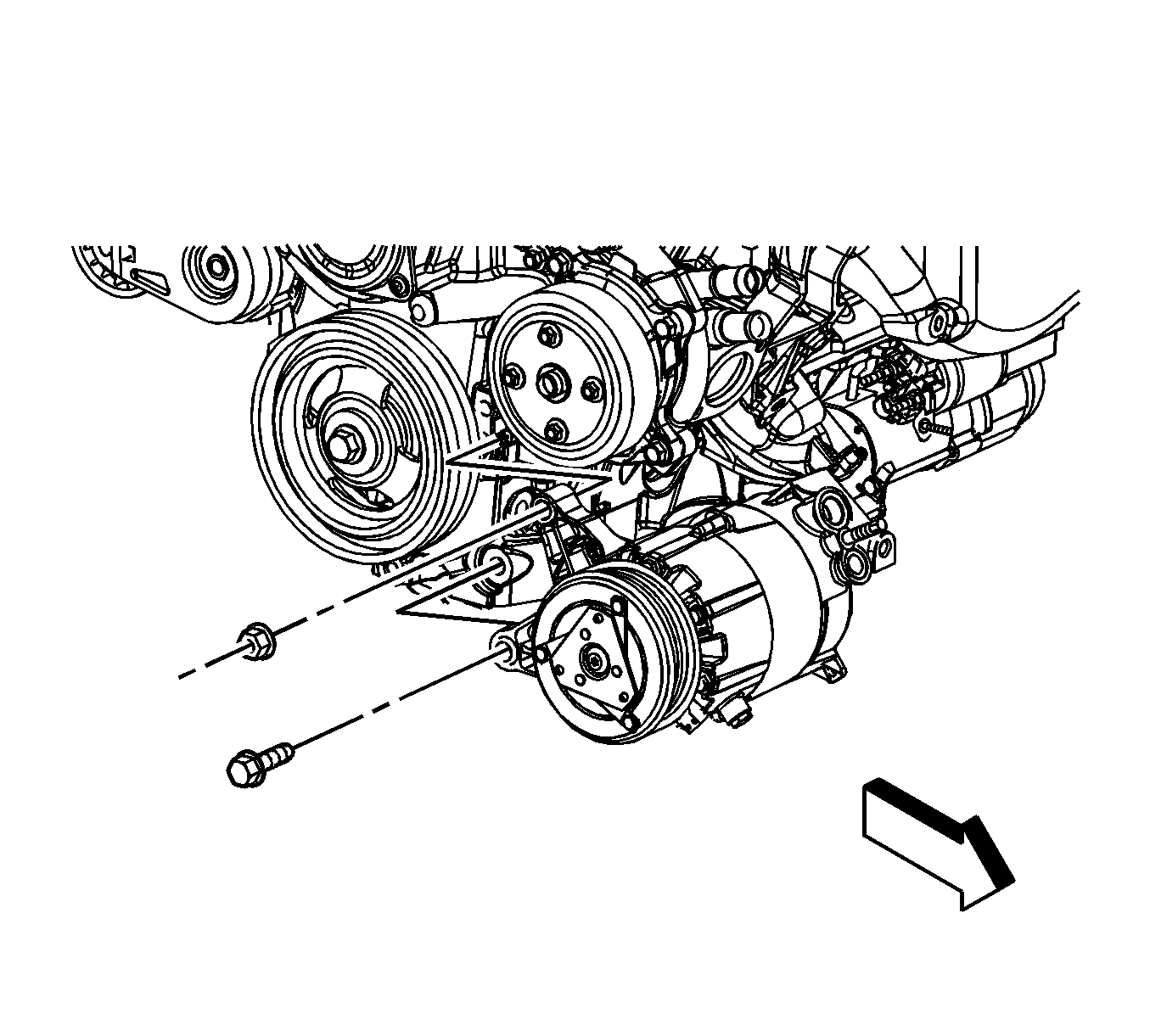
- Remove the A/C compressor front bolt and nut.
- Remove the A/C compressor rear bolt and reposition the compressor off to the side. DO NOT discharge the A/C system.
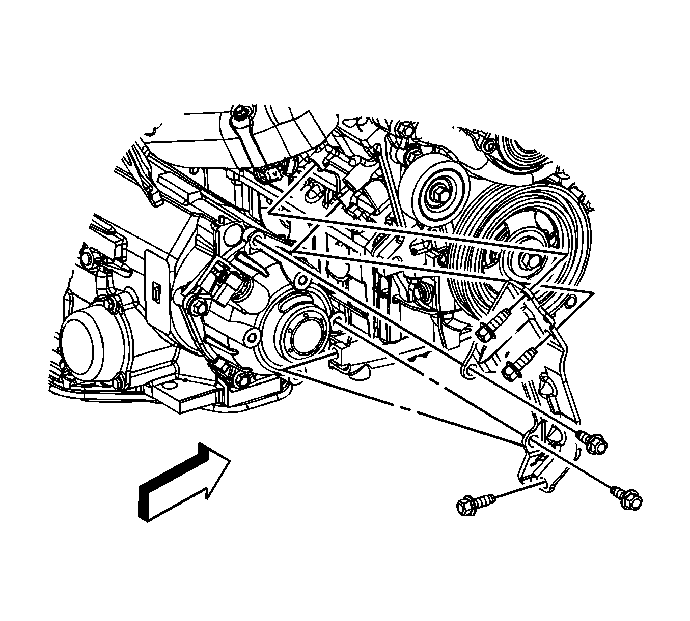
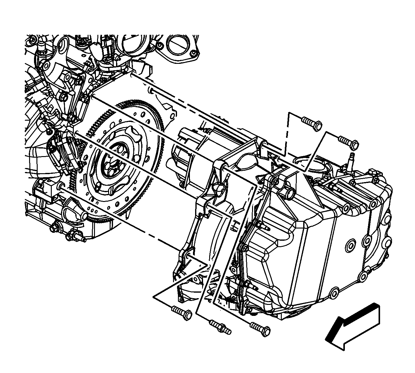
- Remove the transaxle brace to transaxle bolts.
- Remove the transaxle brace to engine bolts.
- Remove the transaxle brace.
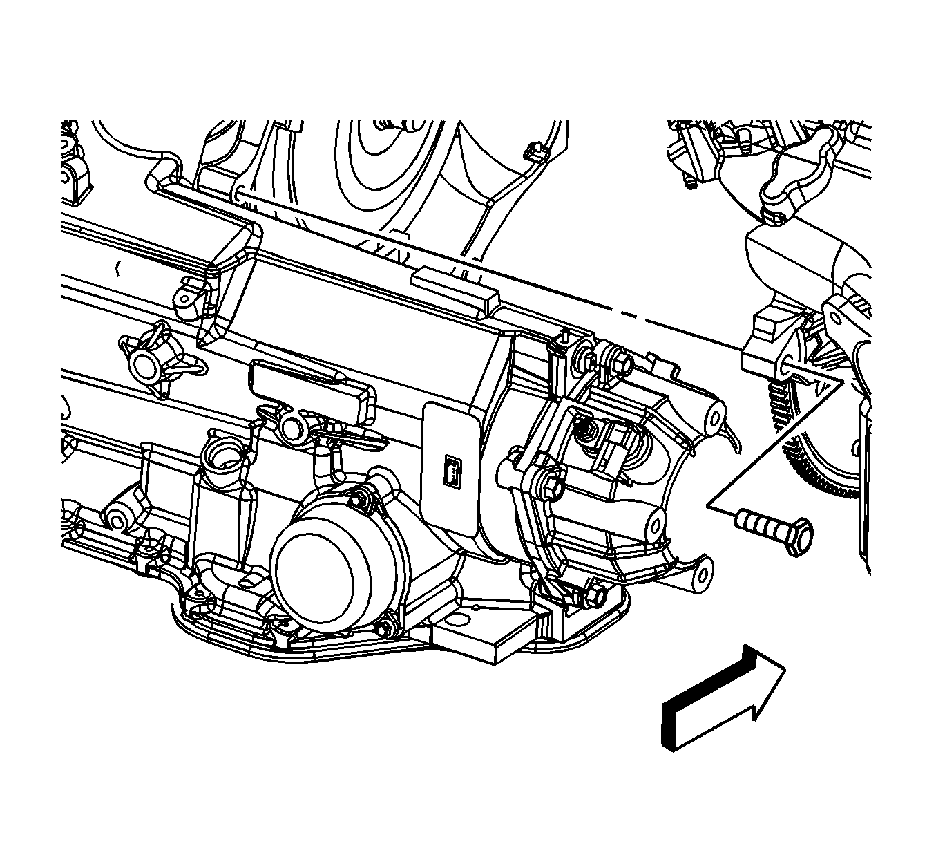
- Remove the transaxle-to-engine lower rear bolt.
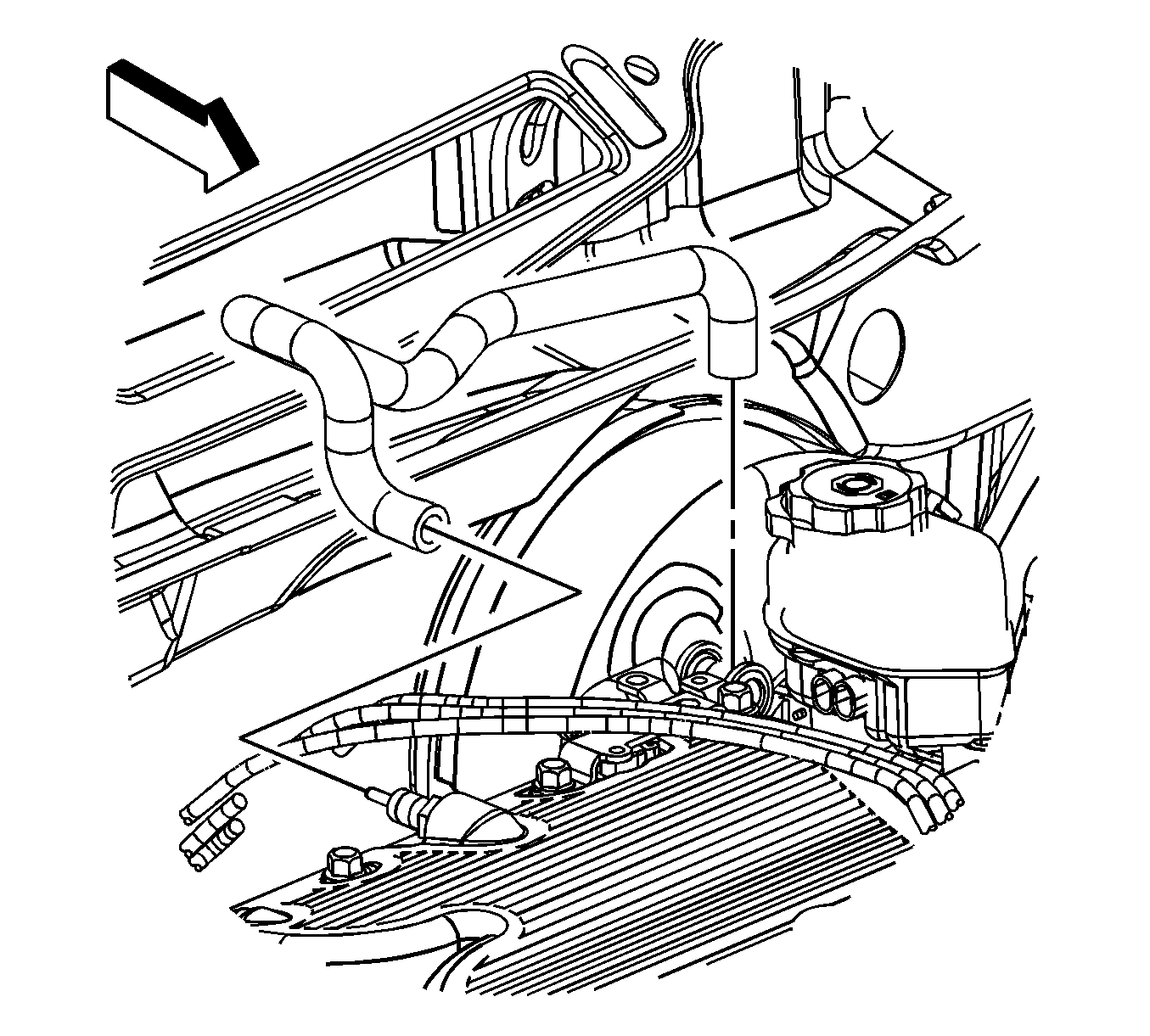
- Reposition the radiator outlet hose clamp at the thermostat housing.
- Remove the radiator outlet hose from the thermostat housing.
- Lower the vehicle and support the transaxle.
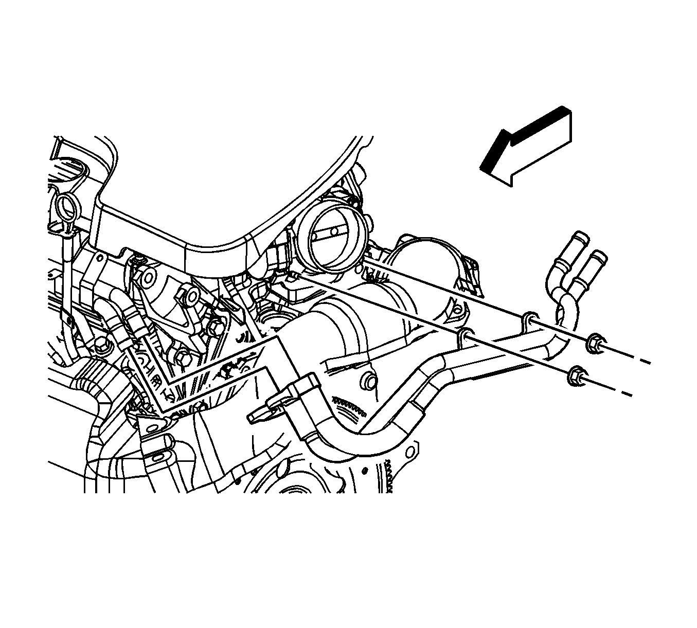
- Remove the brake booster vacuum hose from the intake manifold.
- Reposition the heater inlet and outlet hose clamps at the engine.
- Remove the heater inlet and outlet hoses from the engine pipes.
- Remove the exhaust crossover pipe. Refer to Exhaust Crossover Pipe Replacement.
- Disconnect the fuel feed line from the fuel rail. Refer to Metal Collar Quick Connect Fitting Service.
- Disconnect the EVAP purge line from the canister purge solenoid. Refer to Plastic Collar Quick Connect Fitting Service.
- Reposition the radiator inlet hose clamp at the engine.
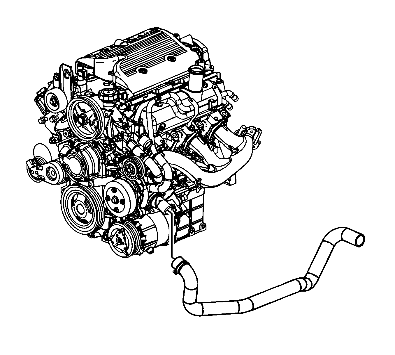
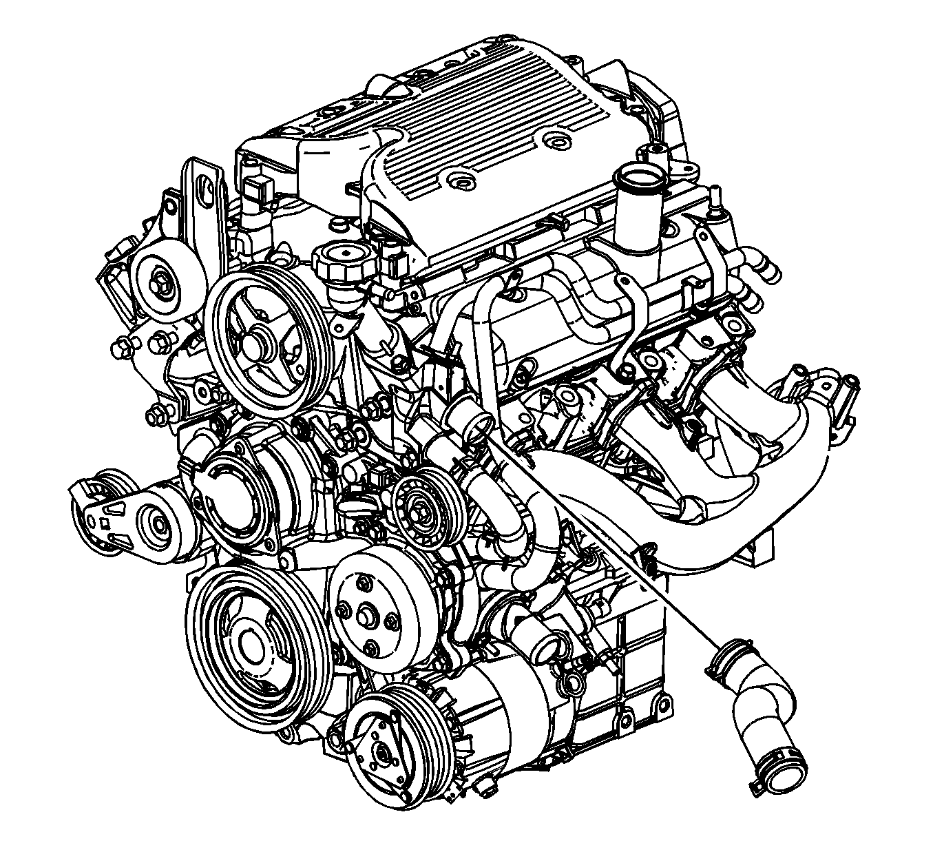
- Remove the radiator inlet hose from the engine.
- Remove the power steering pump bolts and reposition. Refer to Power Steering Pump Replacement.
- Install a engine lifting device to the engine.
- Remove the transaxle-to-engine bolts/studs.
- Remove the engine from the vehicle.
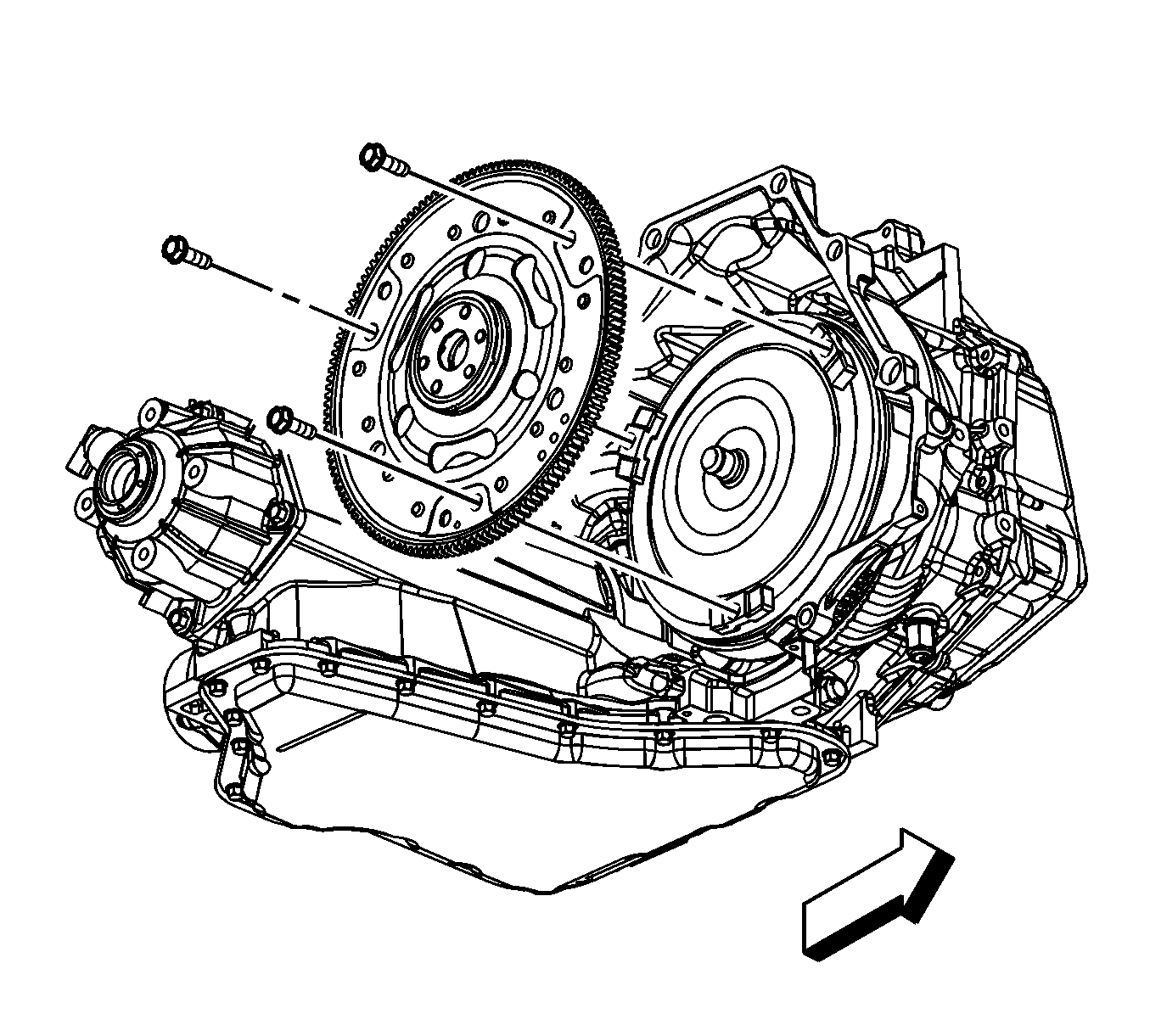
- Remove the flywheel. Refer to Engine Flywheel Removal.
- Install the engine to a engine stand.
Installation Procedure
- Install a engine lifting devise to the engine.
- Remove the engine from the engine stand.
- Install the flywheel. Refer to Engine Flywheel Removal.
- Install the engine to the vehicle.
- Install the transaxle-to-engine bolts/studs.
- Remove the engine lifting device from the engine.
- Position and install the power steering pump bolts. Refer to Power Steering Pump Replacement.
- Install the radiator inlet hose to the engine.
- Position the radiator inlet hose clamp at the engine.
- Connect the EVAP purge line to the canister purge solenoid. Refer to Plastic Collar Quick Connect Fitting Service.
- Connect the fuel feed line to the fuel rail. Refer to Metal Collar Quick Connect Fitting Service.
- Install the exhaust crossover pipe. Refer to Exhaust Crossover Pipe Replacement.
- Install the heater inlet and outlet hoses to the engine pipes.
- Position the heater inlet and outlet hose clamps at the engine.
- Install the brake booster vacuum hose to the intake manifold.
- Install the radiator outlet hose to the thermostat housing.
- Position the radiator outlet hose clamp at the thermostat housing.
- Raise and support the vehicle.
- Install the transaxle-to-engine lower rear bolt.
- Install the transaxle brace.
- Install the transaxle brace to engine bolts.
- Install the transaxle brace to transaxle bolts.
- Position the A/C compressor and install the compressor front bolt and nut.
- Install the A/C compressor rear bolt.
- Install the torque converter bolts.
- Install the starter motor. Refer to Starter Motor Replacement.
- Install the torque converter cover. Refer to Torque Converter Cover Replacement.
- Install the engine mount lower nuts.
- Install the catalytic converter. Refer to Catalytic Converter Replacement.
- Position the engine harness over the engine.
- Position the engine harness ground terminals (1) to the transmission.
- Install the engine harness ground bolt (2).
- Install the engine harness clip bolt (3) to the transmission.
- Connect the CKP sensor electrical connector (4).
- Connect the knock sensor electrical connector (1).
- Install the engine harness clips (2, 3) to the transaxle brace.
- Lower the vehicle.
- Connect the rear upper HO2S electrical connector (2).
- Install the CPA retainer (3).
- Install the engine harness clip (4) to the transaxle bracket.
- Install the engine harness clip bolt (3).
- Connect the camshaft phasor sensor electrical connector (2).
- Connect the fuel injector inline (1) electrical connector.
- Install the engine harness clips (2, 3) to the brackets.
- Connect the ignition coil electrical connector (6).
- Connect the generator electrical connector (3).
- Install the generator terminal (4).
- Install the generator terminal nut (5).
- Position the generator terminal boot (2).
- Connect the MAP sensor electrical connector (1).
- Connect the ETC (2) electrical connector.
- Connect the EVAP canister purge solenoid (1) electrical connector.
- Raise the vehicle.
- Connect the oil level sensor electrical connector.
- Install the engine harness clips to the transaxle brace and the oil pan.
- Connect the A/C compressor electrical connector (4).
- Connect the starter motor electrical connector (3)
- Connect the knock sensor (2) electrical connector.
- Connect the oil pressure sensor (1) electrical connector.
- Install the oil pressure sensor heat shield and nuts.
- Lower the vehicle.
- Install the engine mount struts. Refer to Engine Mount Strut Replacement.
- Install the drive belt. Refer to Drive Belt Replacement.
- Install the air cleaner assembly. Refer to Air Cleaner Assembly Replacement.
- Install the hood. Refer to Hood Replacement.
- Fill the engine with oil. Refer to Engine Oil and Oil Filter Replacement.
- Fill the cooling system. Refer to Cooling System Draining and Filling.
- Install the intake manifold cover. Refer to Intake Manifold Cover Replacement.
- Connect the negative battery cable. Refer to Battery Negative Cable Disconnection and Connection.
Caution: Refer to Fastener Caution in the Preface section.
Tighten
Tighten the bolts/stud to 75 N·m (55 lb ft).
Tighten
Tighten the bolt to 75 N·m (55 lb ft).
Tighten
Tighten the bolts to 63 N·m (46 lb ft).
Tighten
Tighten the bolt/nut to 50 N·m (37 lb ft).
Tighten
Tighten the bolt to 50 N·m (37 lb ft).
Tighten
Tighten the bolts to 63 N·m (46 lb ft).
Tighten
Tighten the nuts to 50 N·m (37 lb ft).
Tighten
Tighten the bolt to 25 N·m (18 lb ft).
Tighten
Tighten the bolt to 25 N·m (18 lb ft).
Tighten
Tighten the nut to 30 N·m (22 lb ft).
Tighten
Tighten the nuts to 10 N·m (89 lb in).
