For 1990-2009 cars only
Removal Procedure
- Raise and suitably support the vehicle. Refer to Lifting and Jacking the Vehicle .
- Remove the wheels. Refer to Tire and Wheel Removal and Installation .
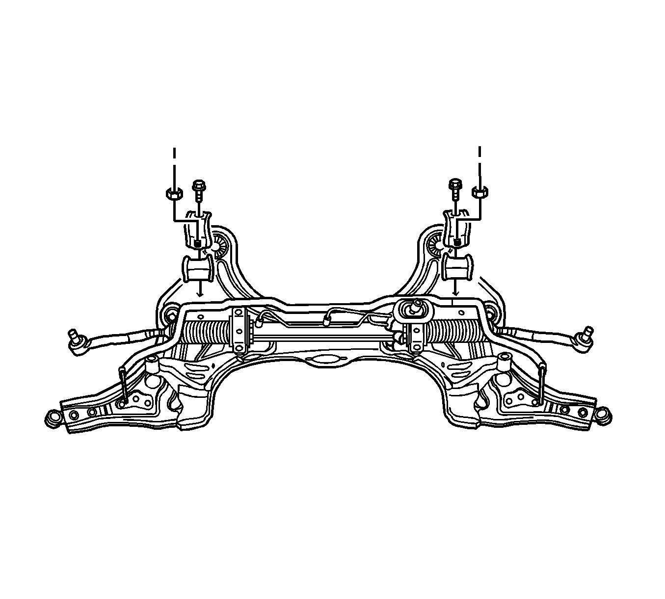
- Remove the nuts and bolts from the steering gear mounting bracket.
- Remove the return line bolt from the clip on the crossmember.
- Remove the exhaust pipe forward of the catalytic converter. Refer to Front Pipe Replacement .
- Disconnect the tie rod from the knuckle assembly. Refer to Rack and Pinion Outer Tie Rod End Replacement .
- Disconnect the ball joint from the knuckle assembly. Refer to Steering Knuckle Replacement .
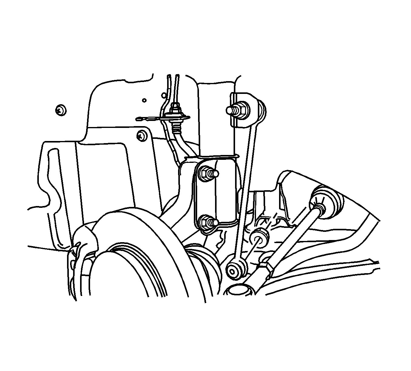
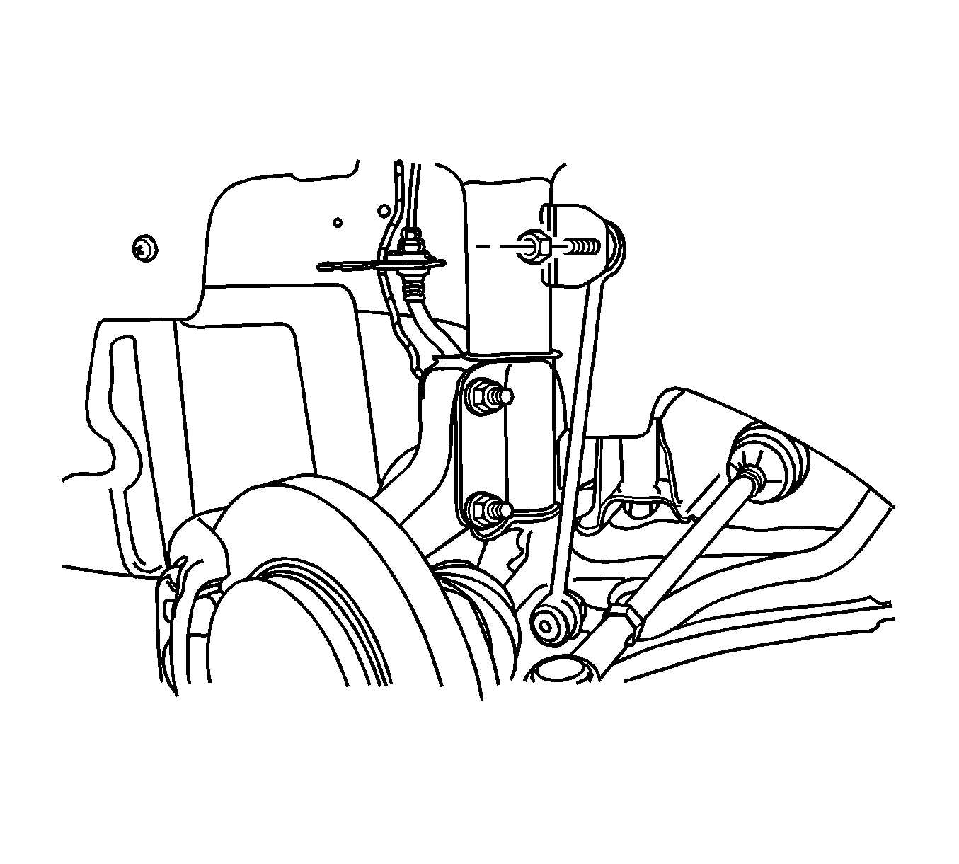
- Disconnect the stabilizer link from the strut assembly. Refer Stabilizer Shaft Link Replacement .
- Remove the crossmember link-to-transaxle bracket nut.
- Support the crossmember with a transaxle support jack.
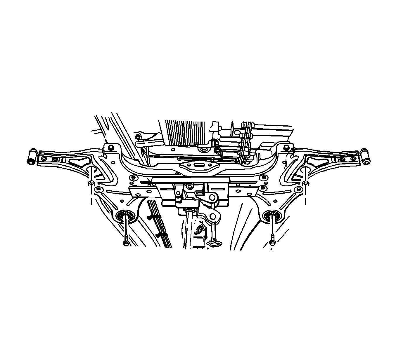
- Remove the rear crossmember-to-body bolts.
- Remove the front crossmember-to-body bolts.
- Lower the crossmember assembly from the vehicle.


Installation Procedure
- Raise the crossmember assembly with a transaxle support jack.
- Install the rear crossmember-to-body bolts.
- Install the front crossmember-to-body bolts.
- Install the bolts and nuts on the steering gear mounting brackets.
- Install the return line bolt into the clip on the crossmember.
- Install the crossmember link-to-transaxle bracket nut.
- Connect the stabilizer link to the strut assembly. Refer Stabilizer Shaft Link Replacement .
- Connect the ball joint to the knuckle assembly. Refer to Steering Knuckle Replacement .
- Connect the tie rod to the knuckle assembly. Refer to Rack and Pinion Outer Tie Rod End Replacement .
- Install the exhaust pipe into the vehicle. Refer to Front Pipe Replacement .
- Install the wheels. Refer to Tire and Wheel Removal and Installation .
- Lower the vehicle.

Notice: Refer to Fastener Notice in the Preface section.
Tighten
Tighten the rear crossmember-to-body bolts to 196 N·m (145 lb ft).
Tighten
Tighten the front crossmember-to-body bolts to 130 N·m (96 lb ft).

Tighten
Tighten the steering gear mounting bracket bolts and nuts to 60 N·m (44 lb ft).
Tighten
Tighten the return line clip bolt to 8 N·m (71 lb in).

Tighten
Tighten the crossmember link-to-transaxle nut to 169 N·m (125 lb ft).
