Tools Required
Starter Motor No-Load Test
Caution: Keep fingers and tools away from the opening in the starter
drive housing while performing the Starter No Load Test. The strong shifting
action of the solenoid could cause personal injury or damage as the drive
pinion moves into the cranking position and spins.
- Remove the starter motor from the vehicle. Refer to
Starter Motor Replacement
.
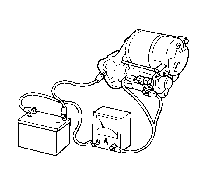
- Connect test leads from
the battery and the ammeter to the starter motor. The pinion should extend
quickly and completely and the starter motor should run smoothly.
- Measure the starter motor current draw. The starter motor current
draw at 11 volts is 90 amperes. Refer to
Starter Motor Usage
.
Evaluation
Rated current draw and no-load speed indicate the normal
condition of the starter motor.
Low free speed and high current draw indicate the following conditions:
| • | Too much friction caused by tight, worn or dirty bushings, or
by a bent armature that allows the armature to drag. |
| • | Shorted armature. Inspect for a shorted armature on a growler
after disassembly. |
| • | Grounded armature or fields. Inspect further after disassembly. |
Failure to operate and high current draw indicates the following conditions:
| • | A direct ground in the terminal or fields |
Failure to operate and low or no current draw indicates the following
conditions:
| • | Open field circuit. Inspect the field circuit after disassembly
by inspecting internal connections. |
| • | Open armature coils. Inspect the commutator for badly burned bars
after disassembly. |
| • | High insulation between the commutator bars |
| • | Other conditions that may prevent good contact between the brushes
and the commutator. |
Low no-load speed and low current draw indicates the following conditions:
| • | High internal resistance due to poor connections |
| • | Open field circuit. Inspect the condition of the internal components
after disassembly in order to find an open field circuit. |
| • | Open armature coils. Inspect the commutator for badly burned bars
after disassembly. |
| • | High insulation between the commutator bars or other conditions
which may prevent contact between the brushes and the commutator. |
High free speed and high current draw indicate shorted fields. If the
fields are shorted, replace the field coil assembly. Use a growler in order
to inspect for a shorted armature.
If any of the above conditions are unsatisfactory, refer to
Starter Motor Overhaul
.
Starter Motor Pull-In, Hold-In and Pinion Return Testing
Notice: Do not allow the solenoid pull-in current to flow for more
than 15 seconds at a time. The windings can be damaged by overheating. Also,
the current draw readings will decrease as the windings heat up.
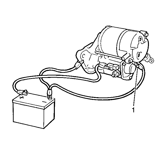
- Remove the field coil lead wire from the solenoid terminal C (1).
- Install the test leads from the battery to the starter motor.
- Ensure that the pinion extends quickly and completely to the energized
position (pull-in test).
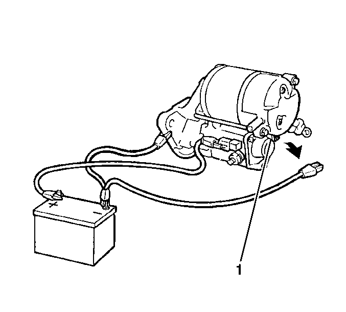
- Remove the negative lead
from the solenoid terminal C (1).
- Verify that the pinion remains completely in the energized position
(hold-in test).
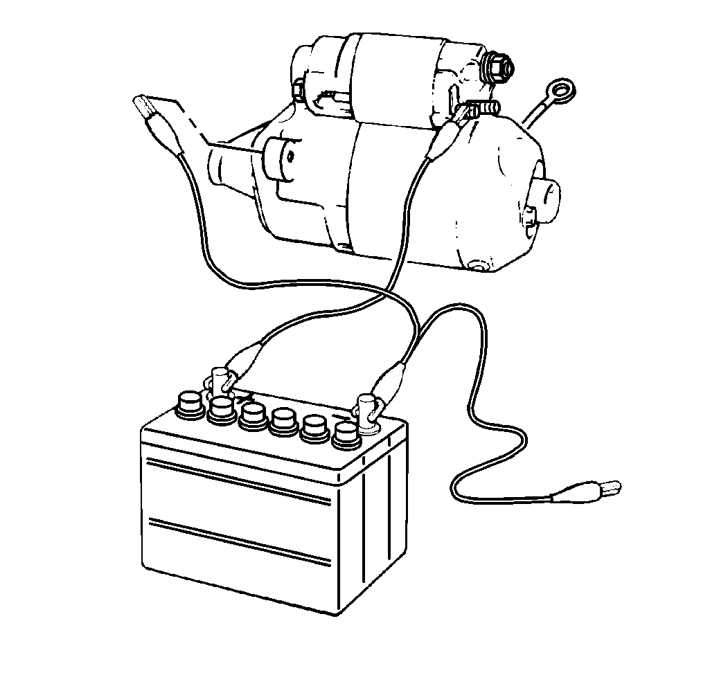
- Remove the negative lead
from the drive housing.
- Ensure that the pinion returns quickly and completely to the de-energized
position (pinion return test).
- If the pinion does not return to the de-energized position, the
cause is most likely a faulty starter solenoid return spring. Replace the
starter solenoid.
- If any of the above tests are not satisfactory, replace the starter
solenoid.
Notice: Use the correct fastener in the correct location. Replacement fasteners
must be the correct part number for that application. Fasteners requiring
replacement or fasteners requiring the use of thread locking compound or sealant
are identified in the service procedure. Do not use paints, lubricants, or
corrosion inhibitors on fasteners or fastener joint surfaces unless specified.
These coatings affect fastener torque and joint clamping force and may damage
the fastener. Use the correct tightening sequence and specifications when
installing fasteners in order to avoid damage to parts and systems.
- Install the field
coil lead wire to the solenoid terminal.
Tighten
Tighten the nut to 6 N·m (52 lb in).
- Install the starter motor to the vehicle. Refer to
Starter Motor Replacement
.
Starter Motor Overhaul-Disassembly Procedure
- Remove the starter motor from the vehicle. Refer to
Starter Motor Replacement
.
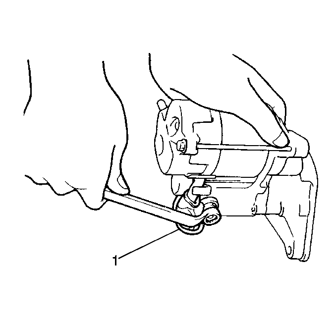
- Remove the nut and the
solenoid wire (1) from the solenoid assembly.
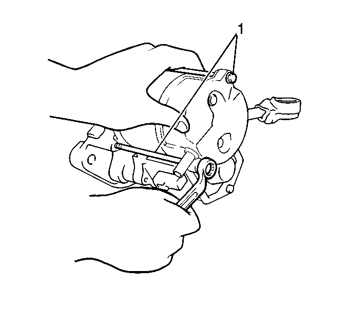
- Remove the two through
bolts (1) and separate the field frame (with armature) from the solenoid
assembly.
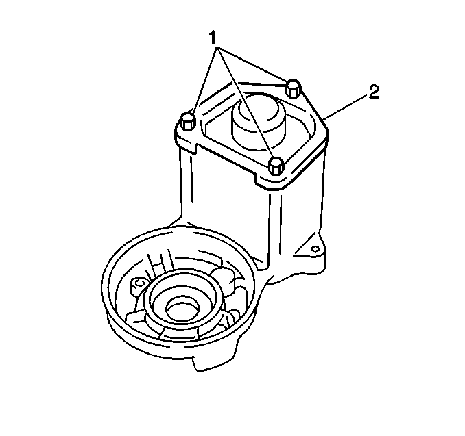
- Remove the three bolts (1)
and the solenoid end cover (2).
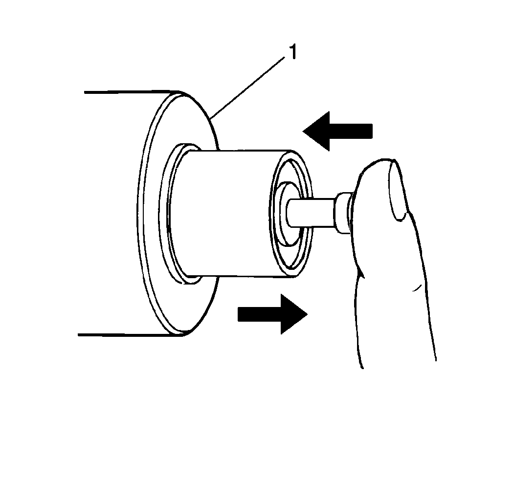
- Inspect the starter solenoid
plunger by pressing the plunger into the starter solenoid (1) and releasing
the plunger. If the plunger does not return to its original position
quickly, replace the starter solenoid.
- Remove the solenoid plunger.
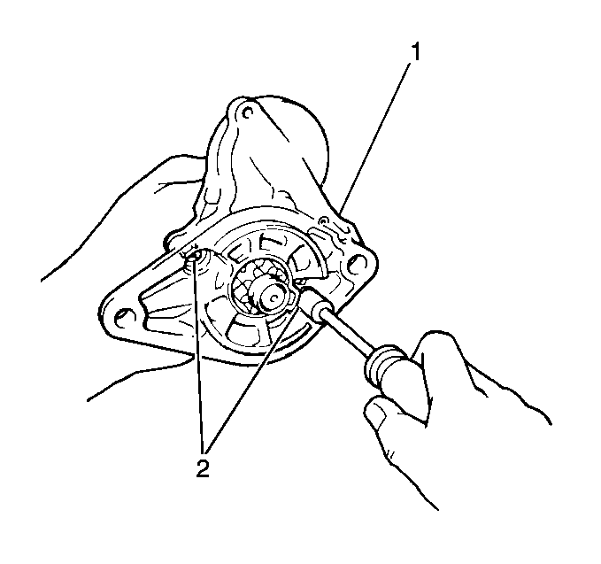
- Remove the two bolts (2)
and separate the drive housing (1) from the solenoid assembly.
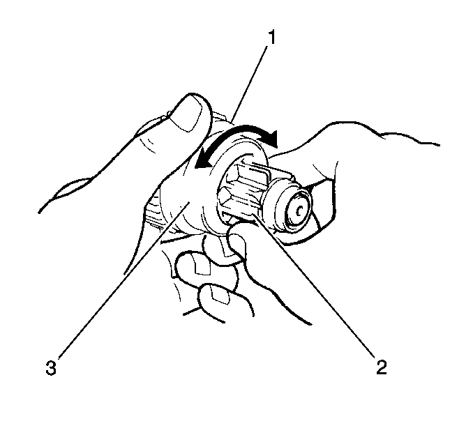
- Inspect the overrunning
clutch (1) for wear, damage and other abnormal conditions.
Verify that the following conditions exist:
| • | The clutch locks when it is turned in the drive direction. |
| • | The clutch rotates smoothly in the reverse direction. |
| • | Replace the clutch assembly as necessary. |
- Inspect the overrunning clutch spline teeth (2) for wear
and damage. Replace the clutch assembly as necessary.
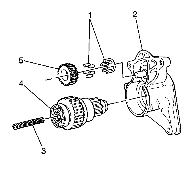
- Remove the idler gear (5)
from the drive housing.
- Carefully remove the idler gear roller bearing (1) from
the drive housing. The needle bearings may fall out during disassembly.
- Remove the return spring (3) from the drive housing.
- Remove the clutch and drive assembly (4) from the drive
housing by gently tapping on the pinion end with a rawhide mallet.
- Inspect the drive housing assembly components for wear, damage
or other abnormalities.
- Replace the components as necessary.
- Inspect the clutch and drive assembly bearings for wear, damage
and smooth operation.
- Replace the bearings as necessary.
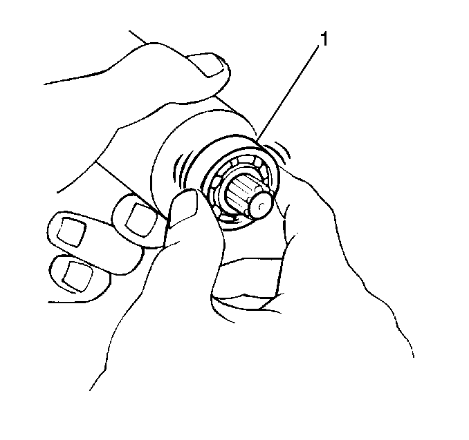
- Inspect the armature
bearings (1) for smooth operation, wear and damage.
- Replace the bearings as necessary.
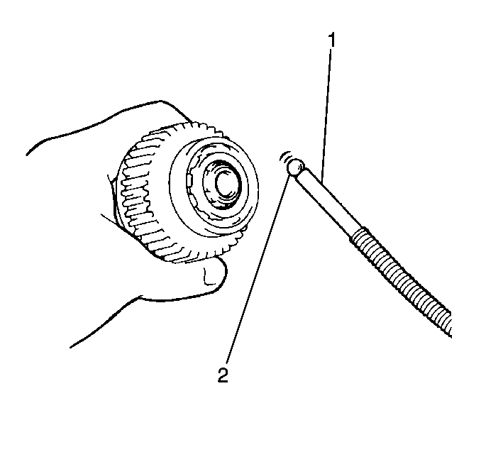
- Remove the steel ball (2)
from the clutch and drive assembly.
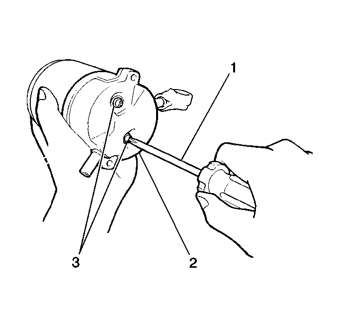
- Remove the following components
from the field frame:
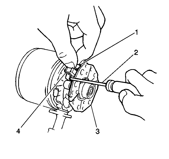
- Remove the brushes.
- Hold the spring back with a small screwdriver (2) and remove
the brush (4) from the brush holder.
- Disconnect the four brushes.
- Remove the brush holder.
- Remove the armature from the field frame.
- Inspect the brush springs for corrosion and damage. Replace the
components as necessary.
- Inspect the brush holder and the insulation on the positive plates
for wear and damage. Replace the components as necessary.
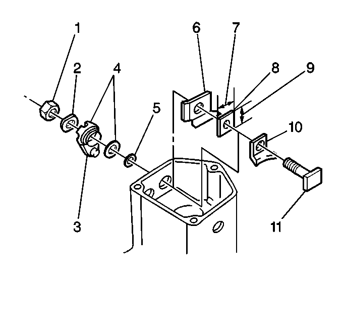
- Remove the following from
terminal 30 of the solenoid assembly:
| • | The outside insulator (4) |
| • | The inside insulator (8) |
| • | The insulation paper (6) |
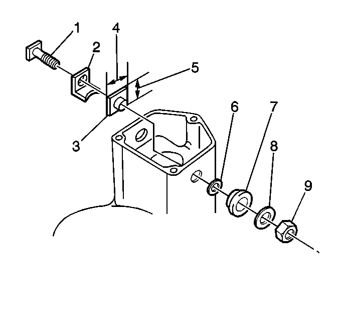
- Remove the following from
terminal C of the solenoid assembly:
| • | The outside insulator (7) |
| • | The inside insulator (3) |
Inspection and Measuring Procedure
Notice: Do not use grease dissolving solvents for cleaning the overrunning clutch
or armature. Solvents dissolve the grease packed in the clutch and damage
the armature and the field coil insulation.
- Clean all of the starter motor parts.
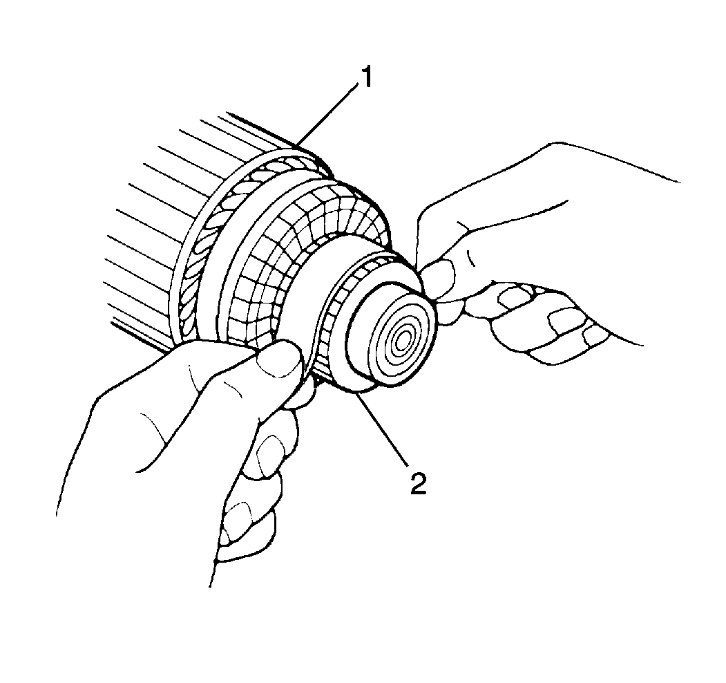
- Remove dirt and burn marks
from the commutator end (2) of the armature (1). Sand the marks
using a #300 or #400 grit sandpaper. Wipe the parts using a
clean shop cloth.
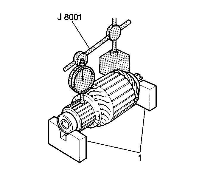
- Place the armature onto
a pair of V-blocks (1).
- Measure the commutator runout using the J 8001
with the J 26900-13
. Replace the armature if the runout exceeds the standard.
Standard Commutator Runout
0.05 mm (0.002 in)
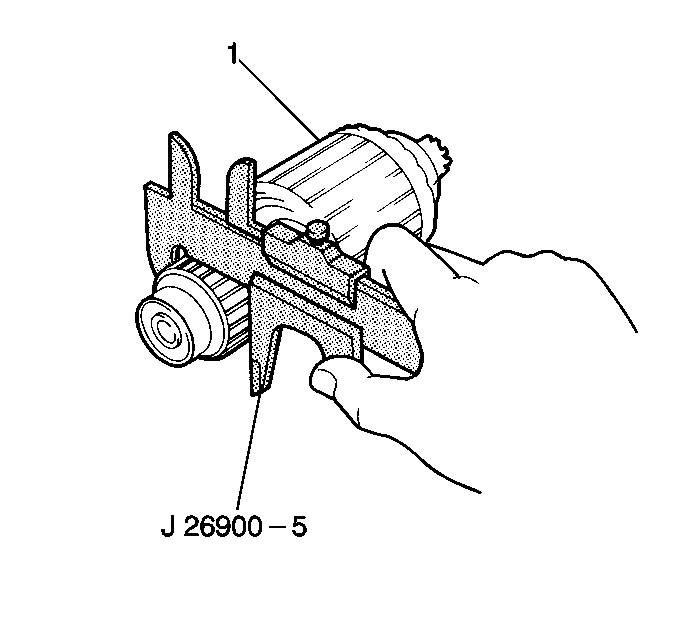
- Measure the commutator
wear using the J 26900-5
.
Replace the armature (1) if the diameter is less than the minimum.
Standard Commutator Diameter
30 mm (1.18 in)
Minimum Commutator Diameter
29 mm (1.14 in)
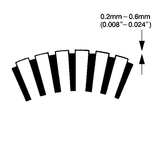
- Measure the commutator
insulation depth. Replace the armature if the insulation depth is less than
the minimum.
Standard Commutator Insulation Depth
0.6 mm (0.024 in)
Minimum Commutator Insulation Depth
0.2 mm (0.008 in)
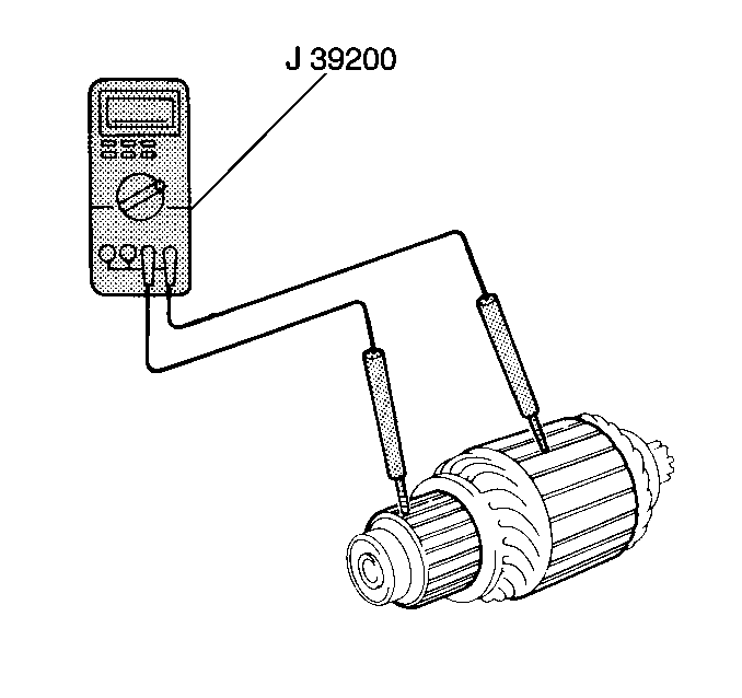
- Measure the resistance
between the armature core and the commutator using the J 39200
. If the resistance is 5.0 ohms
or less, the armature is grounded. Replace the armature.
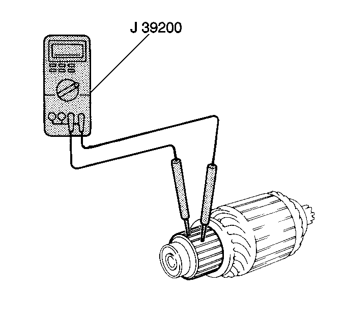
- Measure the resistance
between the commutator segments using the J 39200
. If the resistance is not 5.0 ohms or less
at any test point, there is an open circuit in the commutator.
Replace the armature.
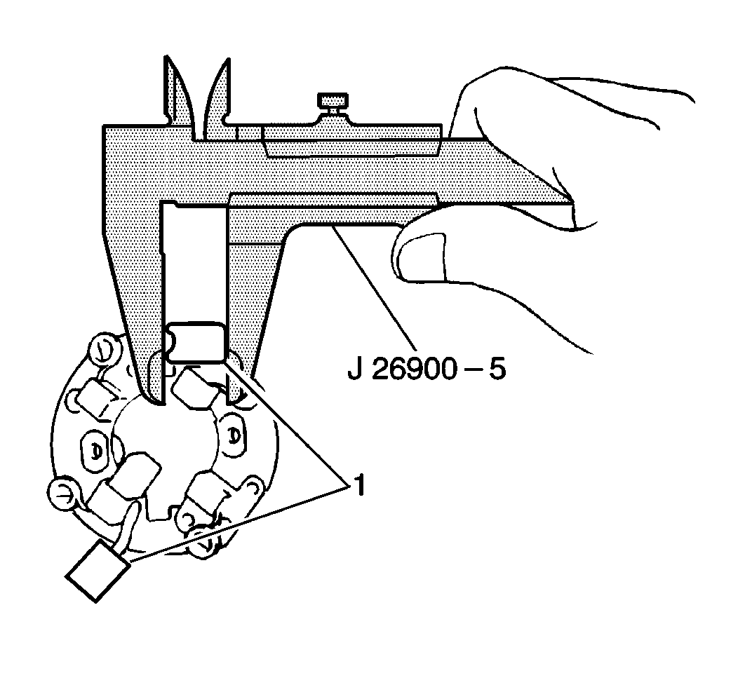
- Measure the positive brush (1)
length using the J 26900-5
.
If the brush length is less than the minimum, replace the brush holder.
Standard Brush Length
15.5 mm (0.610 in)
Minimum Brush Length
10.0 mm (0.394 in)
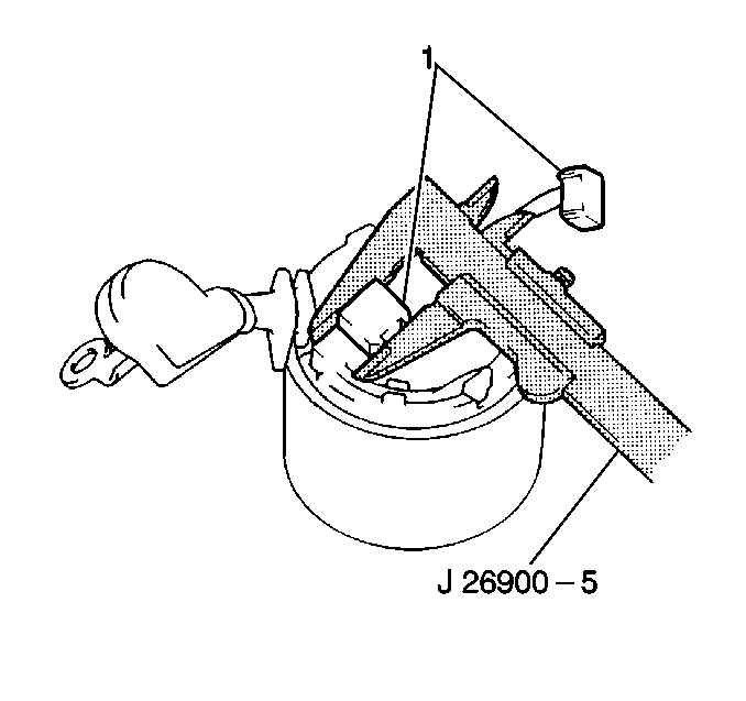
- Measure the negative brush (1)
length using the J 26900-5
.
If the brush length is less than the minimum, replace the field frame.
Standard Brush Length
15.5 mm (0.610 in)
Minimum Brush Length
10.0 mm (0.394 in)
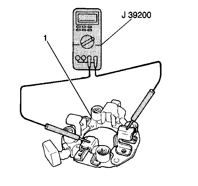
- Measure the resistance
between the positive brush holder and the negative brush holder using the J 39200
. If the resistance is
5.0 ohms or less, the brush holder is grounded. Replace
the brush holder (1).
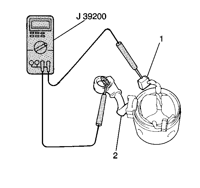
- Measure the resistance
between the lead wire (2) and the field coil brush lead (1)
using the J 39200
. If
the resistance is greater than 5.0 ohms replace the field
frame.
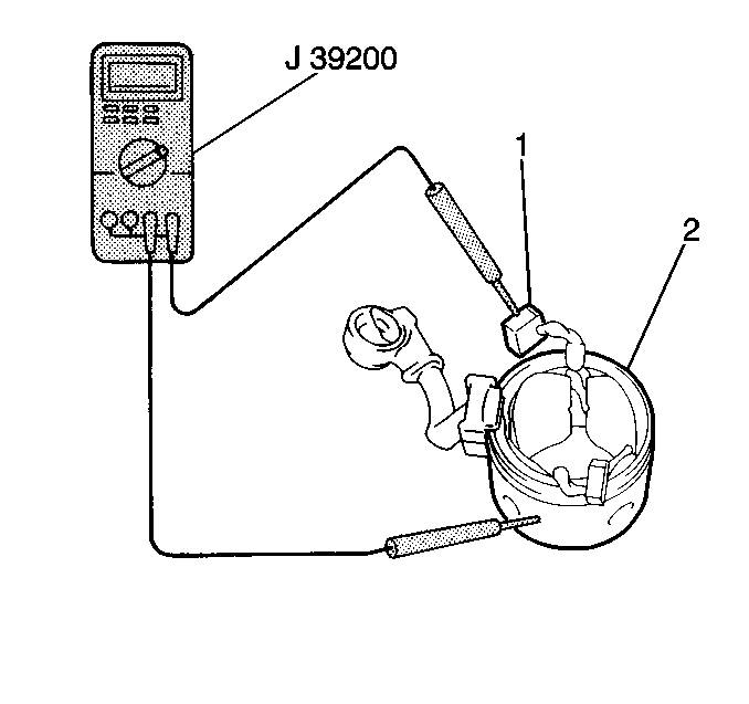
- Measure the resistance
between the field coil brush lead (1) and the field frame (2)
using the J 39200
. If
the resistance is less than 5.0 ohms replace the field
frame.
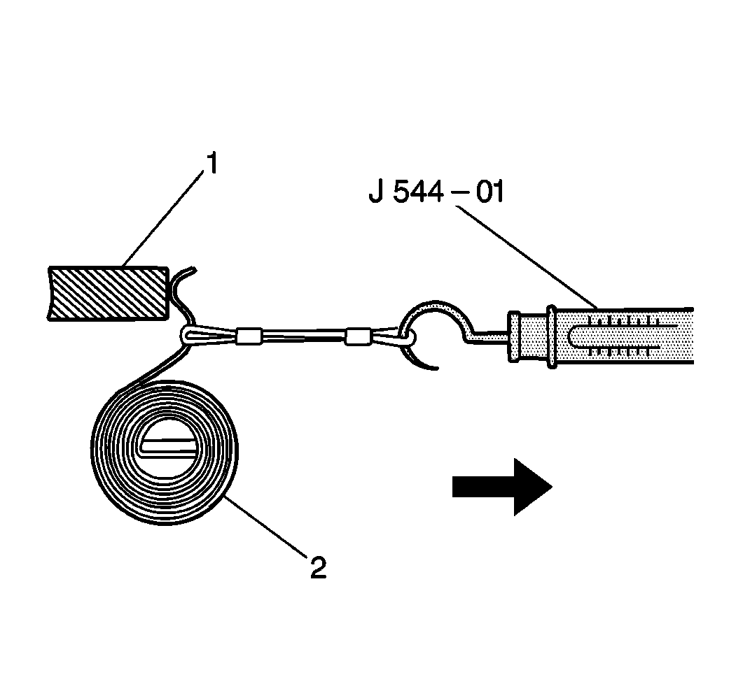
- Measure the brush spring (2)
tension using the J 544-01
.
Take the reading as soon as the brush spring separates from the brush.
If the tension is less than the minimum, replace the brush spring.
Standard Brush Spring Tension
1.8-2.4 kg (4.0-5.3 lb)
Minimum Brush Spring Tension
1.2 kg (2.6 lb)
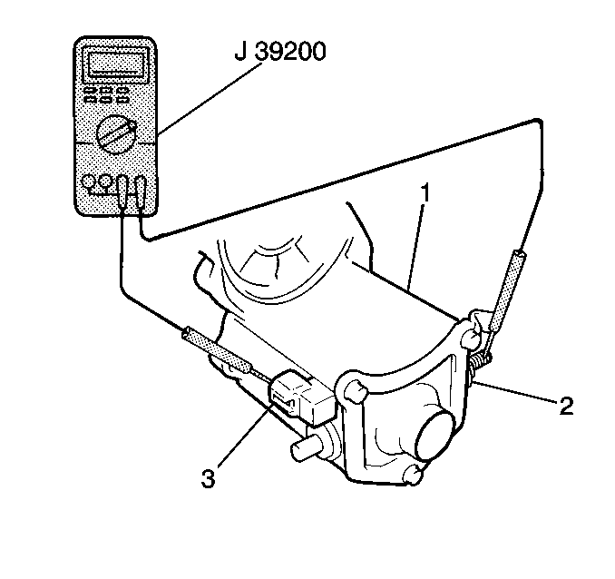
- Measure the starter solenoid
pull in coil resistance between terminals 50 (3) and C (2)
using the J 39200
. If
the resistance is not 5 ohms or less, the pull-in coil
is open. Replace the starter solenoid.
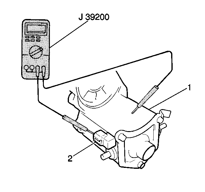
- Measure the starter solenoid
hold-in coil resistance between terminal 50 (2) and the solenoid
case using the J 39200
.
If the resistance is not 5.0 ohms or less, the hold-in
coil is open. Replace the starter solenoid.
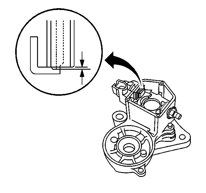
- Measure the contact plate
wear using the J 26900-5
.
If the depth of wear is greater than 0.9 mm (0.035 in)
replace the contact plate.
Starter Motor Overhaul-Assembly Procedure

- Install the following
to terminal 30:
| • | The insulation paper (6) |
| • | The inside insulator (8); long side (7), short side (9) |
| • | The packing and outside insulator (4) |
| | Important: Do not tighten the nut (1) at this time.
|

- Install the following
to terminal C:
| • | The inside insulator (3); long side (4), short side (5) |
| • | The outside insulator (7) |
| | Important: Do not tighten the nut (9) at this time.
|
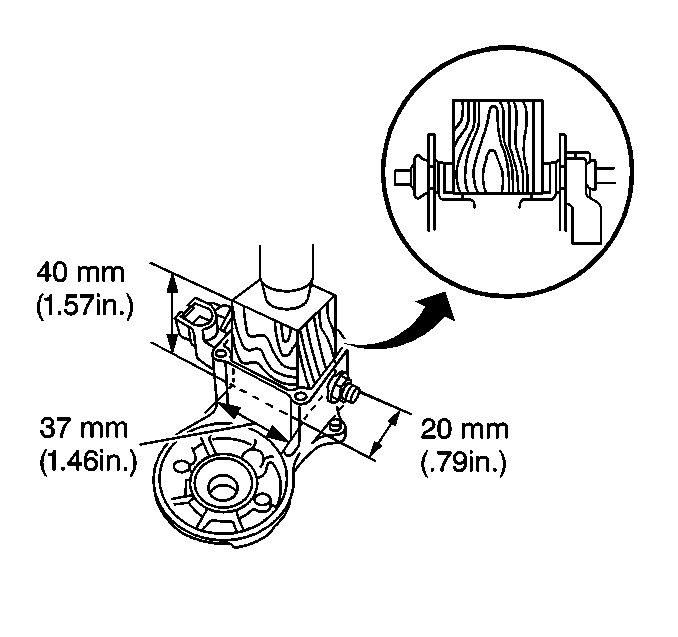
Important: If the contact plate is not pressed down evenly, the contact plate may
tilt due to the tightening of the nut. If the nut is over tightened, it may
cause cracks on the inside of the insulator.
Notice: Use the correct fastener in the correct location. Replacement fasteners
must be the correct part number for that application. Fasteners requiring
replacement or fasteners requiring the use of thread locking compound or sealant
are identified in the service procedure. Do not use paints, lubricants, or
corrosion inhibitors on fasteners or fastener joint surfaces unless specified.
These coatings affect fastener torque and joint clamping force and may damage
the fastener. Use the correct tightening sequence and specifications when
installing fasteners in order to avoid damage to parts and systems.
- Place a wooden block
on the contact plates and press it down with a hand press. Use only enough
force to hold the contact plates firmly seated in the solenoid
assembly. Tighten the nuts.
Dimensions of the wooden block are 20x37x40 mm (0.79x1.46x1.57 in).
Tighten
Tighten the nuts to 17 N·m (12 lb ft).
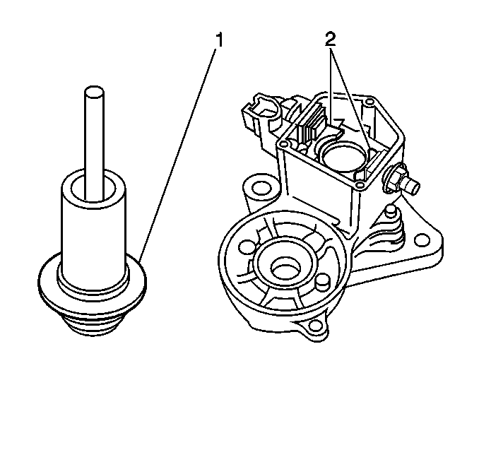
- Clean the contact surfaces
of the contact plates (2) and the plunger (1) with a clean dry
cloth.
- Install the solenoid plunger.
- Install the solenoid end cover.
Tighten
Tighten the nuts to 2.5 N·m (23 lb in).
- Apply a light coating of Lubriplate lubricant GM P/N 1050109,
or an equivalent, to the following locations:
| • | The front armature bearing |
| • | The rear armature bearing |
| • | The idler gear roller bearing |

- Install the armature into
the field frame.
- Install the brush holder.
- Connect the four brushes.
- Hold the spring back with a small screwdriver (2) and install
the brush (4) into the brush holder.

- Install the end cover (2)
to the field frame.
| • | Install the two screws (3) |
Tighten
Tighten the screws to 1.5 N·m (13 lb in).

- Install the steel ball (2)
to the clutch and drive assembly.

- Install the following
to the drive housing:
| • | The idler gear roller bearing (1) |
| • | The clutch and drive assembly (4) |

- Install the drive housing (1)
to the solenoid assembly
Tighten
Tighten the two bolts to 6 N·m (52 lb in).

- Install the field frame
to the solenoid assembly using a new O-ring.
Tighten
Tighten the two through bolts (1) to 6 N·m (52 lb in).

- Install the solenoid lead
wire and nut (1) to the solenoid assembly.
Tighten
Tighten the nut (1) to 6 N·m (52 lb in).
- Install the starter motor to the vehicle. Refer to
Starter Motor Replacement
.


