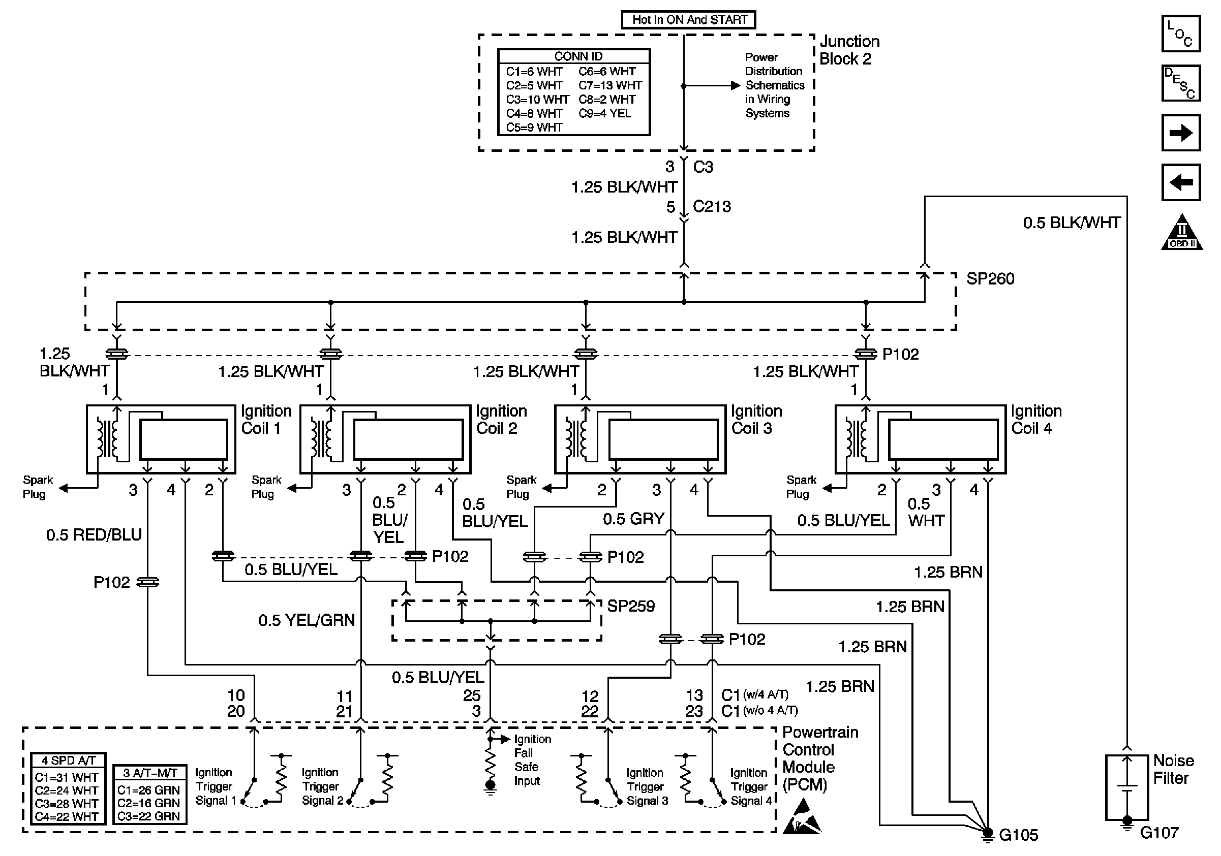
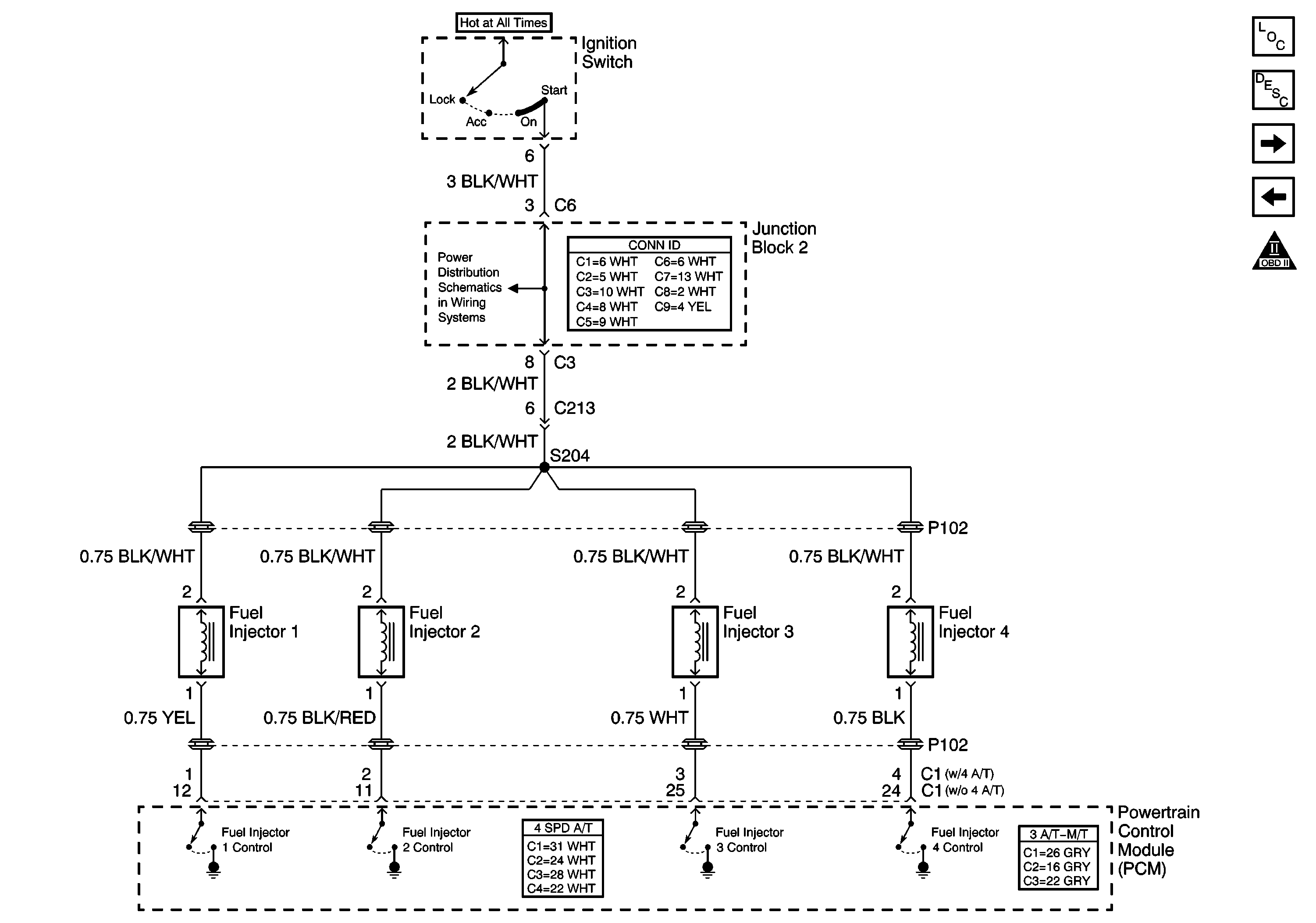
Circuit Description
Each engine cylinder has a dedicated ignition coil assembly. The power distribution circuit supplies system voltage to each ignition module when the ignition switch is In the ON or START positions. The module regulates current flow through the primary coil windings, creating a magnetic field. The PCM signals each module when to supply spark through a control or trigger circuit. The module responds to the trigger circuit signal by opening the circuit of the primary coil, inducing a high voltage in the secondary coil circuit . The high voltage in the secondary circuit flows to ground by arcing at the spark plug and igniting the air/fuel mixture in the combustion chamber. During cranking, the PCM uses the crankshaft position (CKP) sensor and the camshaft position (CMP) sensor signals for optimum fuel delivery and ignition timing. Both the ignition system and the fuel delivery systems depend on input from many sensors in order to operate correctly.
Diagnostic Aids
Check for any of the following conditions:
| • | Insufficient fuel can cause a no start condition. Thoroughly inspect the fuel delivery system for sufficient fuel volume to the fuel injectors. Inspect the fuel supply components for partial blockage or restrictions. |
| • | Fuel injectors with partially blocked and restricted nozzles, or a malfunctioning solenoid, can cause a no start condition. Refer to Fuel Injector Balance Test with Special Tool and Fuel Injector Solenoid Coil Test - Engine Coolant Temperature Between 10-35 Degrees C (50-95 Degrees F) . |
| • | There may be fuel spray at the fuel injectors and the indicated fuel pressure may be correct, yet there may not be enough fuel to start the engine. If the fuel injectors and the injector circuit are OK, and fuel spray is detected, the fuel injector ON time may be inadequate. If the PCM receives incorrect inputs from the various information sensors, the fuel delivered by the fuel injectors may be inadequate to start the engine. Check all the engine data parameters with a scan tool and compare the values indicated with the expected values or the values from a known good vehicle. |
| • | An intermittent condition of cranks but will not start or the engine quits while running can be caused by a PCM shutdown. There will be no fuel, spark, or data communications during a PCM shutdown. A short to ground in the 5 volt reference circuit of the engine data sensors will cause a PCM shutdown. When the short to ground is absent, the PCM will operate normally with no DTCs stored. Check for a shorted TP or FTP sensor, or shorted sensor wiring. |
| • | Check the engine electrical grounds at G106 and G105, both located at the rear of the cylinder head, if the engine has no spark and no fuel injector pulse with no DTCs. |
| • | Check the engine electrical ground G106 if there is spark but no fuel injector pulse. |
| • | If the engine almost starts and then stalls, check for an open in the ground circuits of the CKP sensor and the camshaft position (CMP) sensor. |
| • | Water or foreign material in the fuel can cause a no start or engine will not stay running condition. During freezing weather water can freeze inside the fuel system. The engine may start after 30 minutes in a heated shop. The malfunction may not recur until parked overnight in freezing temperatures. Extreme weather conditions can cause contaminated fuel to prevent the vehicle from starting. |
| • | A vehicle that starts and runs after being brought to the shop for an Engine Cranks But Will Not Run complaint, may have an ignition system that is susceptible to moisture. Spray water on the ignition system components and the wiring in order to check for an engine starting or will not stay running concern. |
An intermittent malfunction may be caused by fault in any of the critical information or component electrical circuits. Inspect the wiring harness and the components for an intermittent condition. Refer to Intermittent Conditions .
Repair any electrical circuit faults that were found. Refer to Wiring Repairs in Wiring Systems.
Test Description
The numbers below refer to the step numbers in the diagnostic table.
-
The Diagnostic System Check-Engine Controls prompts the technician to complete some basic checks and store the Freeze Frame data on the scan tool if applicable. This creates an electronic copy of the data taken when the fault occurred. The information is then stored in the scan tool for later reference.
-
If a fuse is found to be the cause of the no start, locate and repair any shorts that may have caused the fuse to open before replacing the fuse.
-
If there is a fault in either the CKP sensor or CMP sensor circuits, the ignition system can malfunction. Repair the cause of a DTC P0335 or DTC P0340 first.
-
If there is a fault in the electrical circuits between the PCM and the ignition coil assemblies, a DTC P1300-P1315 will set. Use the DTC P1300-P1315 diagnostic table in order to repair the ignition system failure.
-
The fuel mixture may be too rich or too lean to start the engine if the engine coolant temperature (ECT) sensor signal is incorrect.
-
The fuel mixture may be too rich or too lean to start the engine if the throttle position (TP) sensor signal is incorrect.
-
The fuel mixture may be too rich or too lean to start the engine if the mass air flow (MAF) sensor signal is incorrect.
-
This step checks to see if there is any fuel pressure. If there is no fuel pressure the fuel pump electrical circuit must be inspected.
-
This step checks to see if the engine will start and run. The repair that may have led to this step may only have been a secondary cause of the no start condition, such as fouled spark plugs. The diagnostics in this table may need to be performed a second time in order to discover the root cause of the no start condition.
Step | Action | Values | Yes | No | ||||||||||||||||||
|---|---|---|---|---|---|---|---|---|---|---|---|---|---|---|---|---|---|---|---|---|---|---|
Schematic Reference:
| ||||||||||||||||||||||
Did you perform the Diagnostic System Check-Engine Controls? | -- | Go to Step 2 | ||||||||||||||||||||
Was a repair necessary? | -- | Go to Step 17 | Go to Step 3 | |||||||||||||||||||
Check for any DTCs with a scan tool. Is a DTC P0335 or P0340 set? | -- | Go to Step 4 | ||||||||||||||||||||
Is a DTC P1300, P1305, P1310, or P1315 set? | -- | Go to Step 5 | ||||||||||||||||||||
Is the coolant temperature displayed on the scan tool near the actual coolant temperature? | -- | Go to Step 6 | Go to DTC P0115 | |||||||||||||||||||
Observe the TP sensor parameter on a scan tool with the throttle closed. Is the throttle position opening displayed on the scan tool within the specified range? | 0-23% | Go to Step 7 | Go to DTC P0121 | |||||||||||||||||||
Is the MAF reading within the specified range? | 1.80-3.95 g/s | Go to Step 8 | Go to DTC P0101 | |||||||||||||||||||
8 |
Did the fuel injector test lamp flash for each injector while cranking the engine? | -- | Go to Step 9 | |||||||||||||||||||
9 |
Is a crisp blue spark available at all ignition coil assemblies? | -- | Go to Step 10 | |||||||||||||||||||
10 |
Was a repair or replacement necessary? | -- | Go to Step 17 | Go to Step 11 | ||||||||||||||||||
Is the fuel pressure indicated within the specified range? | 301-347 kPa (44-50 psi) | Go to Step 13 | Go to Step 12 | |||||||||||||||||||
12 |
Is the fuel pressure indicated more the specified range? | 0 to 7 kPa (0 to 1.0 psi) | Go to Fuel System Diagnosis | |||||||||||||||||||
13 |
Was a repair necessary? | -- | Go to Step 17 | Go to Step 14 | ||||||||||||||||||
14 |
Was a repair necessary? | -- | Go to Step 17 | Go to Step 15 | ||||||||||||||||||
15 |
Was an engine mechanical concern found and repaired? | -- | Go to Step 17 | Go to Step 16 | ||||||||||||||||||
16 | Inspect the exhaust system for excessive backpressure. Refer to Restricted Exhaust in Engine Exhaust. Was an exhaust system repair or replacement necessary? | -- | Go to Step 17 | Go to Diagnostic Aids | ||||||||||||||||||
Does the engine start and continue to run? | -- | Go to Step 18 | Go to Step 2 | |||||||||||||||||||
18 |
Are any DTCs displayed? | -- | Go to Step 19 | |||||||||||||||||||
19 | With the scan tool review the stored information, Capture Info. Does the scan tool display any DTCs that you have not diagnosed? | -- | System OK | |||||||||||||||||||


