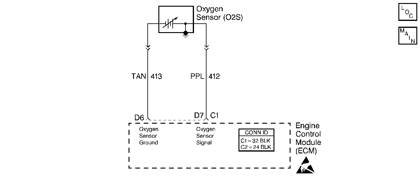
Circuit Description
The ECM supplies a voltage of about 0.45 volt between terminals D6 and D7. (If measured with a J 39200 , this may read as low as 0.32 volt.) The oxygen sensor varies the voltage within a range of about 1.0 volt if the O2S signal is rich, down through about 0.10 volt if O2S signal is lean.
The sensor is like an open circuit and produces no voltage when it is below about 315°C (600°F). An open sensor circuit or cold sensor causes Open Loop operation.
Conditions for Setting the DTC
| • | O2S signal voltage remains below 0.2 volt. |
| • | System is operating in Closed Loop. |
| • | All conditions are met for 20 seconds. |
Action Taken When the DTC Sets
The Malfunction Indicator Lamp (MIL) will illuminate. The system will go Open Loop.
Conditions for Clearing the MIL/DTC
The conditions for the fault are no longer present and 50 ignition cycles have passed with no further faults or the ignition switch is turned OFF and the battery feed voltage is removed for 10 seconds.
Diagnostic Aids
| • | Using the scan tool, observe the long term fuel trim values at different RPM and air flow conditions. If the conditions for a DTC 44 exist, the long term fuel trim values will be around 150. |
| • | Oxygen sensor wire -- The sensor pigtail may be mis-positioned and contacting the exhaust manifold. |
| • | Check for an intermittent ground in the wire between the connector and the sensor. |
| • | Fuel contamination -- Water, even in small amounts near the in-tank fuel pump inlet, can be delivered to the injectors. The water causes a lean O2S signal and can set a DTC 44. |
| • | Fuel pressure -- System will be lean if the pressure is too low. Monitor fuel pressure while driving the vehicle at various road speeds and/or loads in order to confirm. Refer to Fuel System Pressure Test |
| • | If the O2S ground circuit is open, the voltage at terminal D7 will be over one volt. |
| • | If all checks OK, the oxygen sensor is faulty. |
Test Description
The number below refers to the step number on the Diagnostic Table.
Step | Action | Value(s) | Yes | No |
|---|---|---|---|---|
1 | Did you perform the On-Board Diagnostic (OBD) System Check? | -- | ||
Does the scan tool display an oxygen sensor voltage fixed below the specified value? | 75-95°C (167-203°F) 1,200 RPM 0.35 V | Go to Diagnostic Aids | ||
3 |
Does the scan tool display a voltage within the specified value? | 0.35-0.55 V (350-550 mV) | Go to Diagnostic Aids | |
4 |
Did you find a problem? | -- | ||
5 | Replace the ECM. Refer to Engine Control Module Replacement Is the action complete? | -- | -- | |
6 |
Did the DTC reset? | -- | ||
7 | Are any DTCs stored which you have not diagnosed? | -- | Go to the Applicable DTC Table | System OK |
