GM Service Manual Online
For 1990-2009 cars only

Compressor Overhaul Seltec TM-16HD

Disassembly Procedure

  1. Remove the compressor from the engine.
  2. • For the P72, refer to Compressor .
    • For the P92, refer to Compressor .
  3. Remove the compressor magnetic clutch. Refer to Compressor Magnetic Clutch .

  4. Object Number: 22121  Size: SH
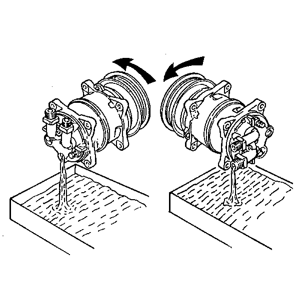
  5. Remove the connector caps, the oil drain and the fill plugs.
  6. 3.1. Discard the O-rings on both of the plugs.
    3.2. Drain the compressor oil.

    Object Number: 22164  Size: SH
  7. Remove the shaft cover and the seal. Refer to Compressor Shaft Seal .
  8. Remove the six body bolts and the six washers from the front cylinder head.

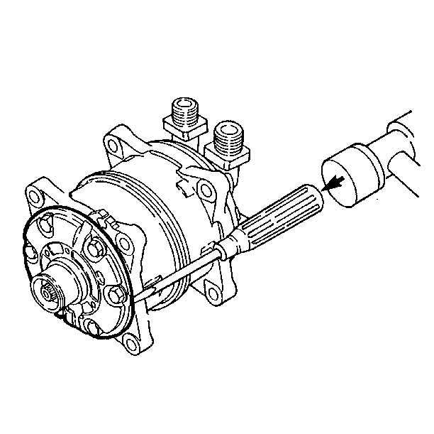
  9. Object Number: 22165  Size: SH
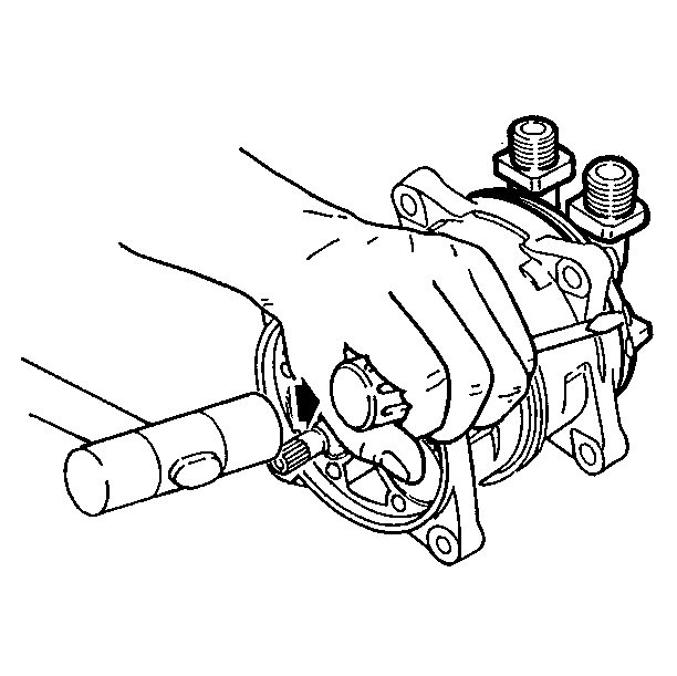
  10. Remove the front cylinder head by tapping the projections on the circumference of the front cylinder head using a screwdriver and a plastic mallet.

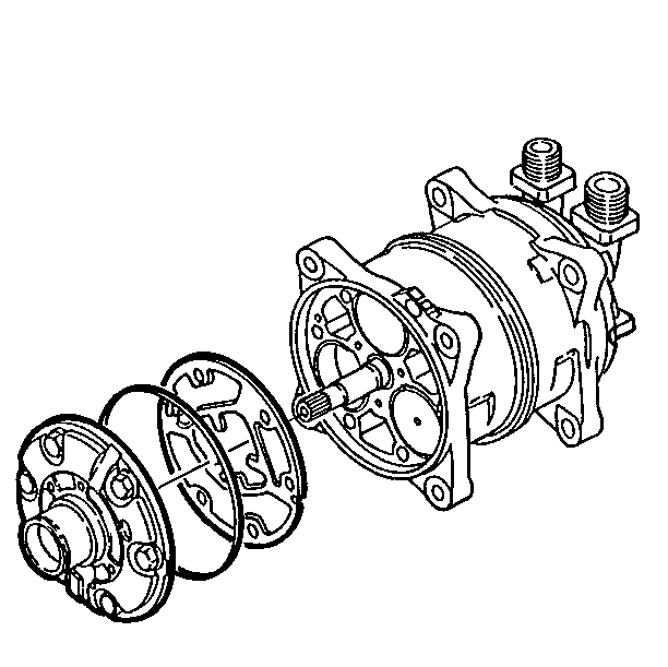
  11. Object Number: 22167  Size: SH
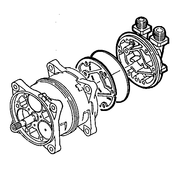
  12. Remove the O-ring and the gasket from the front cylinder head.
  13. Clean all the gasket material that clings to the front cylinder head.

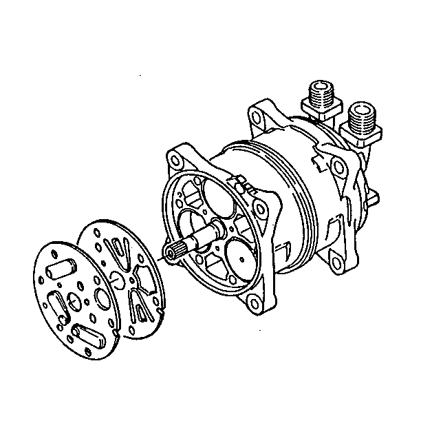
  14. Object Number: 22168  Size: SH
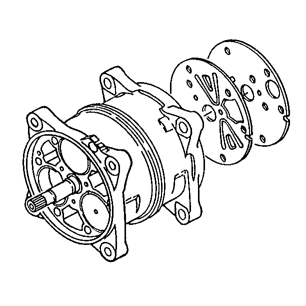
  15. Remove the valve plate and the suction valve from the cylinder shaft assembly.
  16. Clean all the gasket material that clings to the valve plate.

  17. Object Number: 22169  Size: SH
  18. Remove the rear cylinder head by tapping the projections on the circumference of the rear cylinder head using a screwdriver and a plastic mallet.

  19. Object Number: 22171  Size: SH
  20. Remove the O-ring and the gasket from the rear cylinder head.
  21. Clean all the gasket material that clings to the rear cylinder head.

  22. Object Number: 22173  Size: SH
  23. Remove the valve plate and the suction valve from the cylinder shaft assembly.
  24. Clean all the gasket material that clings to the valve plate.

Inspection Procedure

    • Inspect both cylinder heads for nicks or burrs on the sealing surfaces. Replace parts that are scratched on the sealing surfaces.
    • Inspect the front and the rear valve plates for cracked, bent, or damaged parts.
        Replace parts that are cracked, bent, or damaged.
    • Inspect both valve plate assemblies for scratches or burrs on the sealing surfaces. Replace parts that are scratched on the sealing surfaces.
    • Check for obstructions in the passages in the valve plates. Clean out the obstructions.

       Important: Do not disassemble the cylinder shaft assembly. The cylinder shaft assembly is not serviceable.

    • Check the Cylinder shaft assembly for evidence of cracks in the pistons or in the housing. Replace the cylinder shaft assembly.

Assembly Procedure


    Object Number: 22175  Size: SH
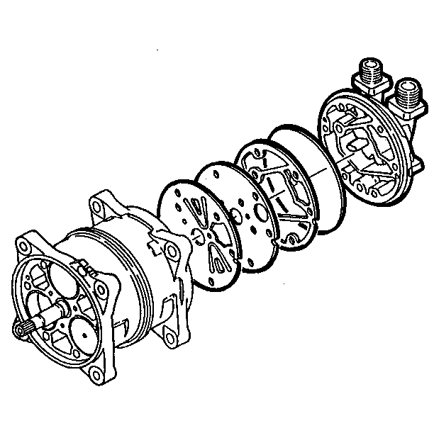
  1. Place the cylinder shaft assembly on the bench with the rear-side facing up. Ensure the front and the rear parts do not get mixed up. The front and rear parts are similar.
  2. Coat the new gaskets and O-rings with compressor oil prior to installation.
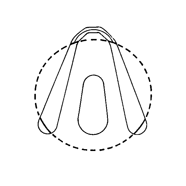
  3. Important: Ensure that the rear suction valve is aligned with the valve escape groove of each cylinder.

  4. Install the rear suction valve so that it is aligned with the alignment pin.
  5. Object Number: 22178  Size: SH
  6. Install the rear valve plate, the new gasket, and the new O-ring on the rear cylinder head.

  7. Object Number: 22175  Size: SH
  8. Install the rear cylinder head on the cylinder shaft assembly.
  9. Turn the cylinder shaft assembly with the rear cylinder head installed over on the bench so that it is front-side up.
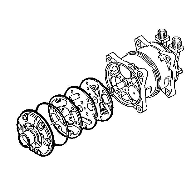
  10. Important: Ensure that the front suction valve is aligned with the valve escape groove of each cylinder.

  11. Install the front suction valve into the cylinder shaft assembly.
  12. Object Number: 22180  Size: SH
  13. Install the front valve plate, the suction valve, a new gasket and a new O-ring on the front cylinder head.
  14. Install the front cylinder head on the cylinder shaft assembly. In order to get the front cylinder head to seat in the cylinder shaft assembly, you may need to lightly tap the front cylinder head with a plastic mallet.
  15. Object Number: 22164  Size: SH
  16. Install new washers and body bolts into the front cylinder head.
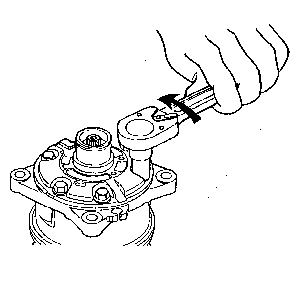
  17. Tighten
    Tighten the body bolts to 20-24 N·m (14.5-17.3 lb ft).

    Notice: Use the correct fastener in the correct location. Replacement fasteners must be the correct part number for that application. Fasteners requiring replacement or fasteners requiring the use of thread locking compound or sealant are identified in the service procedure. Do not use paints, lubricants, or corrosion inhibitors on fasteners or fastener joint surfaces unless specified. These coatings affect fastener torque and joint clamping force and may damage the fastener. Use the correct tightening sequence and specifications when installing fasteners in order to avoid damage to parts and systems.

  18. Tighten the body bolts in sequence. Each bolt should be gradually tightened in three or more stages to ensure the correct torque.
  19. Object Number: 22182  Size: SH
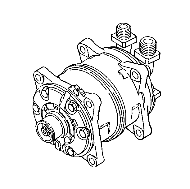
  20. Rotate the drive shaft by hand 2-3 times to ensure that the shaft turns smoothly after tightening the body bolts.
  21. Object Number: 22116  Size: SH
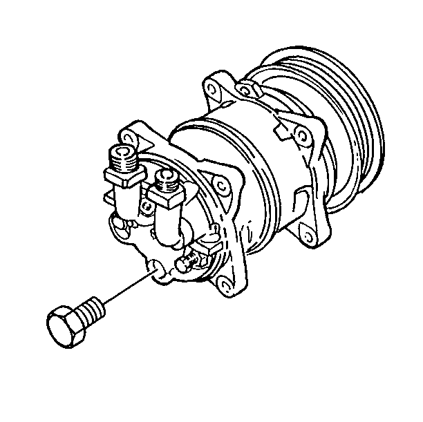
  22. Install new O-rings, the oil drain, and the fill plugs.
  23. Tighten
    Tighten the oil drain and the fill plugs to 13-15N·m (9.4-10.8 lb ft).

    Object Number: 22184  Size: SH
  24. Install the compressor magnetic clutch and the pulley. Refer to Compressor Magnetic Clutch .
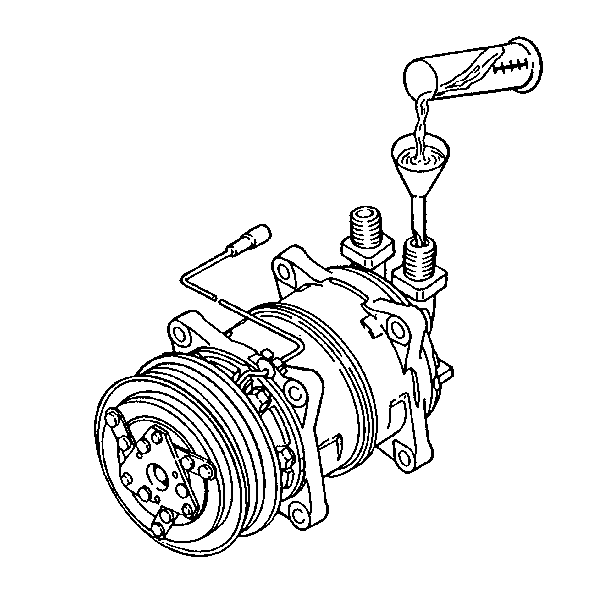
  25. Fill the compressor with oil through the suction-side hose connector. Use the quantity of oil shown on the information plate that is attached to the compressor housing.
  26. Turn the drive shaft 2-3 times by hand to ensure the following:
  27. • The shaft rotates smoothly.
    • Any oil in the cylinders is removed.
  28. Install the compressor onto the engine.
  29. • For the P72, refer to Compressor .
    • For the P92, refer to Compressor .
  30. Perform a leak test on the compressor. Refer to Leak Testing or the coach manufacturer's service manual for leak testing procedures.