Accessory Mounting Brackets Replacement Left
Removal Procedure
- Disconnect both the battery negative cables from the batteries. Refer to Battery Negative Cable Disconnection and Connection in Engine Electrical.
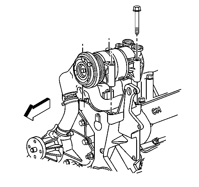
- Remove the air conditioning compressor from the accessory bracket (if equipped), and position to the side.
- Remove the fan shroud from the radiator. Refer to Fan Shroud Replacement in Engine Cooling.
- Remove the drive belt from the pulleys. Refer to Drive Belt Replacement .
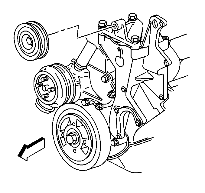
- Remove the idler pulley assembly the left accessory bracket (non A/C shown).
- Remove the auxiliary generator (if equipped) from the accessory bracket. Refer to Auxiliary Generator Replacement in Engine Electrical.
- Drain the cooling system. Refer to Auxiliary Generator Replacement in Engine Cooling.
- Remove the engine cooling fan from the vehicle. Refer to Fan Shroud Replacement in Engine Cooling.
- Remove the heater hose from the thermostat housing and position out of the way.
- Remove the thermostat housing crossover from the cylinder heads. Refer to Thermostat Housing Crossover Replacement in Engine Cooling.
- Remover the power steering pump from the accessory bracket. Refer to Power Steering Pump Replacement in Power Steering System.
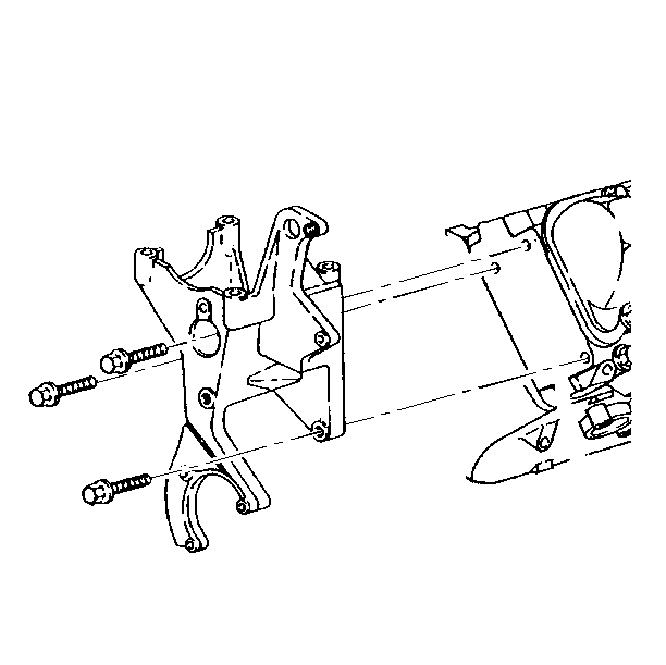
- Remove the bolts from the accessory bracket.
- Remove the accessory bracket from the engine block.
Installation Procedure
- Install the accessory bracket to the engine block.
- Install the accessory bracket bolts to the cylinder head.
- Install the power steering pump to the accessory bracket. Refer to Power Steering Pump Replacement in Power Steering System.
- Install the thermostat housing crossover to the cylinder heads. Refer to Thermostat Housing Crossover Replacement in Engine Cooling.
- Install the heater hose to the thermostat housing.
- Install the A/C compressor to the accessory bracket.
- Install the idler pulley assembly to the left accessory bracket (non A/C shown). Refer to Drive Belt Idler Pulley Replacement .
- Install the auxiliary generator (if equipped) to the left accessory bracket. Refer to Auxiliary Generator Replacement in Engine Electrical.
- Install the engine cooling fan to the vehicle. Refer to Fan Clutch Replacement in Engine Cooling.
- Install the drive belt on the pulleys. Refer to Drive Belt Replacement .
- Install the fan shroud in the vehicle. Refer to Fan Shroud Replacement in Engine Cooling.
- Refill the cooling system. Refer to Cooling System Draining and Filling in Engine Cooling.
- Connect both the battery negative cables to the batteries. Refer to Battery Negative Cable Disconnection and Connection in Engine Electrical.

Notice: Use the correct fastener in the correct location. Replacement fasteners must be the correct part number for that application. Fasteners requiring replacement or fasteners requiring the use of thread locking compound or sealant are identified in the service procedure. Do not use paints, lubricants, or corrosion inhibitors on fasteners or fastener joint surfaces unless specified. These coatings affect fastener torque and joint clamping force and may damage the fastener. Use the correct tightening sequence and specifications when installing fasteners in order to avoid damage to parts and systems.
Tighten
Tighten the bolts to 50 N·m (37 lb ft).


Accessory Mounting Brackets Replacement Right
Removal Procedure
- Disconnect both the battery negative cables from the batteries. Refer to Battery Negative Cable Disconnection and Connection in Engine Electrical.
- Remove the fan shroud from the radiator. Refer to Fan Shroud Replacement in Engine Cooling.
- Remove the drive belt from the pulleys. Refer to Drive Belt Replacement .
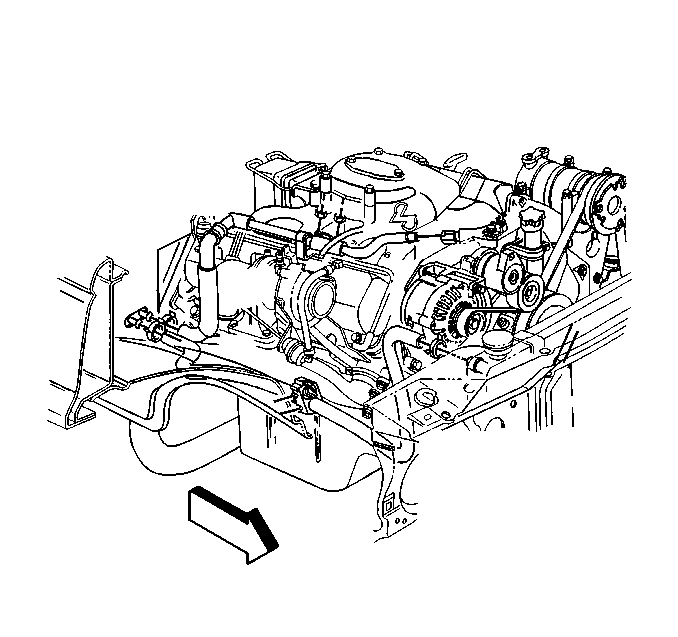
- Remove the generator from the accessory bracket and position to the side.
- Remove the drive belt tensioner from the accessory bracket. Refer to Drive Belt Tensioner Replacement .
- Remove the vacuum pump from the accessory bracket. Refer to Vacuum Pump Replacement .
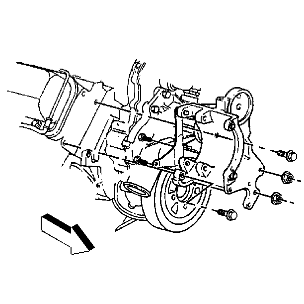
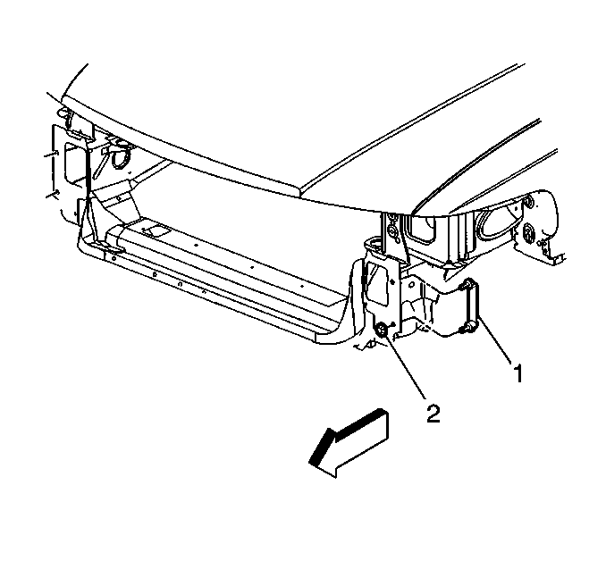
- Remove the accessory bracket bolts from the engine block.
- Remove the accessory bracket from the vehicle.
Installation Procedure
- Install the accessory bracket to the vehicle.
- Install the accessory bracket bolts to the engine block.
- Install the vacuum pump to the accessory bracket. Refer to Vacuum Pump Replacement .
- Install the drive belt tensioner to the right accessory bracket. Refer to Drive Belt Tensioner Replacement .
- Install the generator to the accessory bracket.
- Install the drive belt on the pulleys. Refer to Drive Belt Replacement .
- Install the fan shroud to the radiator. Refer to Fan Shroud Replacement in Engine Cooling.
- Connect both the battery negative cables to the batteries. Refer to Battery Negative Cable Disconnection and Connection in Engine Electrical.

Notice: Use the correct fastener in the correct location. Replacement fasteners must be the correct part number for that application. Fasteners requiring replacement or fasteners requiring the use of thread locking compound or sealant are identified in the service procedure. Do not use paints, lubricants, or corrosion inhibitors on fasteners or fastener joint surfaces unless specified. These coatings affect fastener torque and joint clamping force and may damage the fastener. Use the correct tightening sequence and specifications when installing fasteners in order to avoid damage to parts and systems.
Tighten
Tighten the bolts to 50 N·m (37 lb ft).
Tighten
Tighten the nuts to 50 N·m (37 lb ft).

