For 1990-2009 cars only
Support Replacement GNC
Special Tools
EN-49411 Angle Meter
For equivalent regional tools, refer to Special Tools.
Removal Procedure
- Raise and support the vehicle. Refer to Lifting and Jacking the Vehicle.
- Remove the rear tire and wheel assemblies. Refer to Tire and Wheel Removal and Installation.
- Remove the rear muffler assembly. Refer to Exhaust Muffler Replacement.
- Disconnect the stabilizer shaft from stabilizer shaft links. Refer to Stabilizer Shaft Replacement.
- Remove the park brake cables from the support. Refer to Parking Brake Rear Cable Replacement.
- Remove the rear axle lower control arms from the vehicle. Refer to Rear Axle Lower Control Arm Replacement.
- Remove the adjust links from the from the vehicle. Refer to Adjust Link Replacement.
- Remove rear axle upper control arm inner fasteners. Refer to Rear Axle Upper Control Arm Replacement.
- Position a transmission jack under the rear support and firmly secure the support to the jack with straps.
- Mark the position of the support to the body with spray paint.
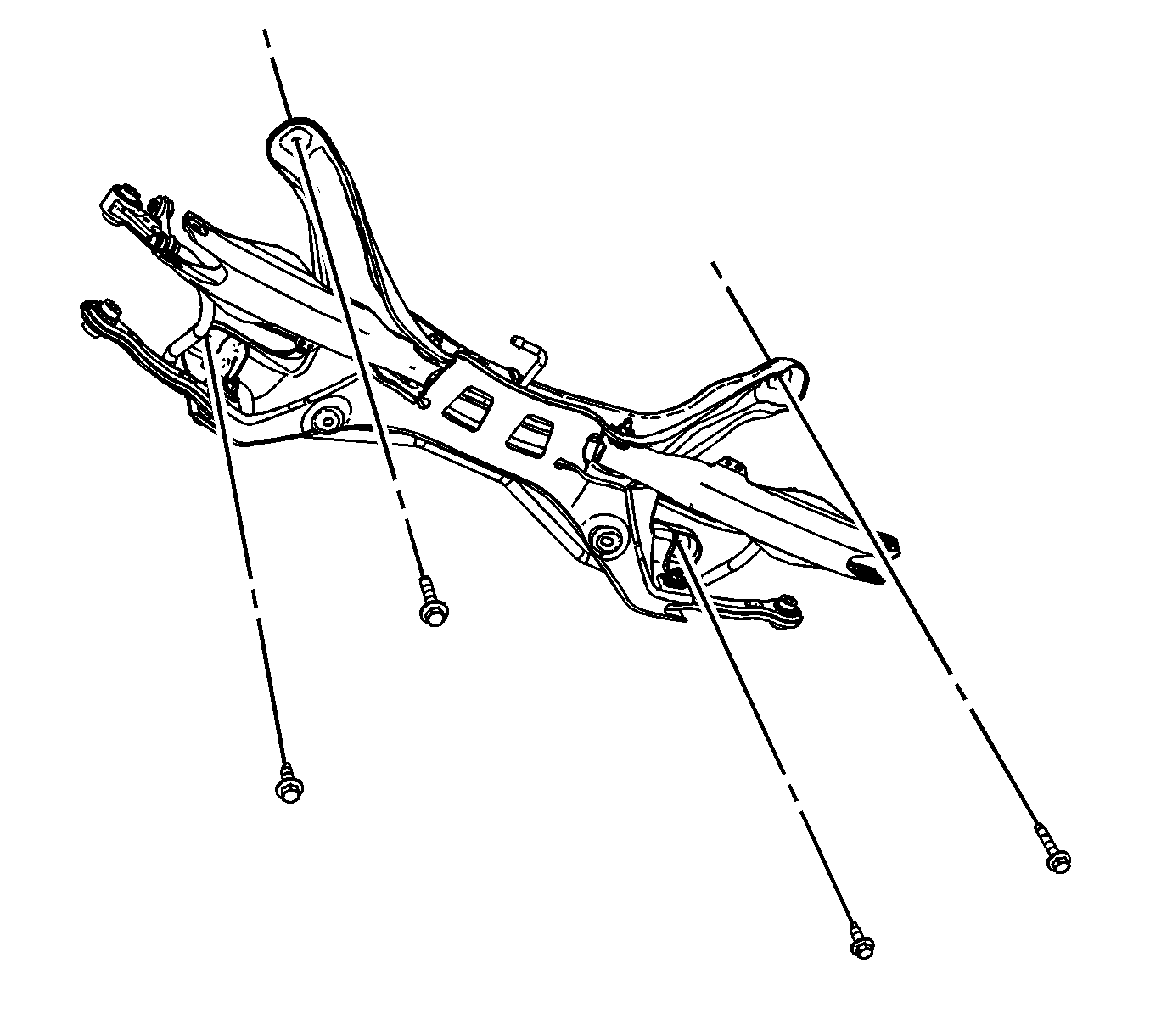
- Remove the support bolts and discard them.
- With the aid of an assistant, lower the support from the transmission jack stand.
- Remove the stabilizer shaft from the rear support.

Installation Procedure
- Install the stabilizer shaft assembly on to the support. Refer to Stabilizer Shaft Replacement.
- With the aid of an assistant, position the rear support onto the transmission jack and firmly secure the support to the jack with straps.
- Install the NEW support bolts and tighten to 90 N·m (66 lb ft).
- Tighten the support bolts an additional 120 degrees + 15 degrees using the EN-49411 angle meter .
- Remove the transmission jack stand.
- Install the rear axle upper control arm inner fasteners. Refer to Rear Axle Upper Control Arm Replacement.
- Install the adjust links to the support. Refer to Adjust Link Replacement.
- Install the rear axle lower control arms. Refer to Rear Axle Lower Control Arm Replacement.
- Install the park brake cables to the rear support. Refer to Parking Brake Rear Cable Replacement.
- Install the rear muffler assembly. Refer to Exhaust Muffler Replacement
- Connect the stabilizer shaft links to the stabilizer shaft. Refer to Stabilizer Shaft Replacement.
- Install the rear tire and wheel assemblies. Refer to Tire and Wheel Removal and Installation.
- Lower the vehicle.
- Realign the rear suspension. Refer to Wheel Alignment Measurement.
Note: When transferring any suspension components, refer to each suspension component replacement procedure for the proper torque specifications.
Caution: Refer to Fastener Caution in the Preface section.

Support Replacement GNE
Removal Procedure
- Raise and support the vehicle. Refer to Lifting and Jacking the Vehicle.
- Remove the tires and wheels. Refer to Tire and Wheel Removal and Installation.
- Remove the exhaust muffler. Refer to Exhaust Muffler Replacement.
- Remove the park brake cables from the support. Refer to Parking Brake Rear Cable Replacement.
- Remove shock absorber lower fastener. Refer to Shock Absorber Replacement.
- Remove rear wheel speed sensor. Refer to Rear Wheel Speed Sensor Replacement.
- Remove the lower control arms from the vehicle. Refer to Rear Axle Lower Control Arm Replacement.
- Remove the upper control arms from the vehicle. Refer to Rear Axle Upper Control Arm Replacement.
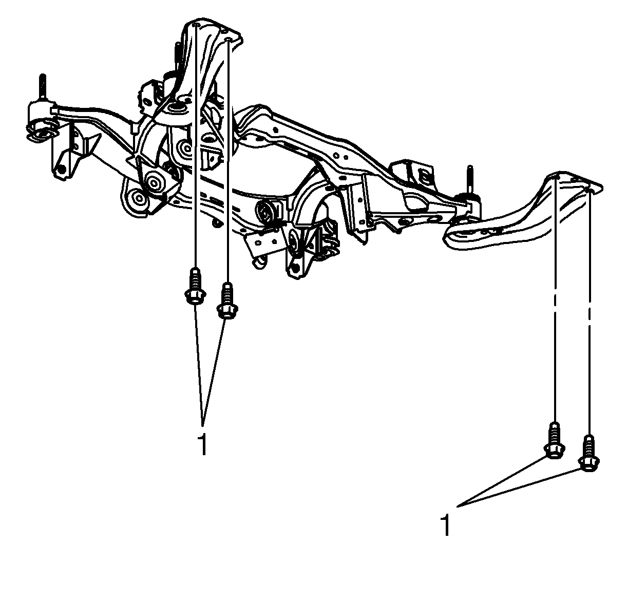
- Remove reinforcement arm bolts (1) to body.
- Remove the outer fastener adjustment links. Refer to Adjust Link Replacement.
- Remove the rear wheel drive shafts. Refer to Rear Wheel Drive Shaft Replacement.
- Remove the rear axle. Refer to Rear Axle Replacement.
- Position a transmission jack under the rear support and firmly secure the support to the jack with straps.
- Mark up support position to body with spray paint.
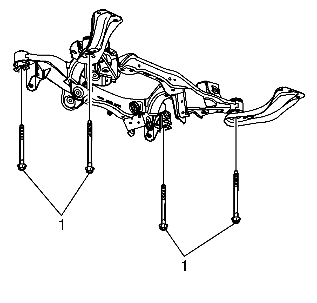
- Remove the 4 rear support to body bolts (1).
- Remove the rear support assembly from the vehicle.
- Remove the inner fastener from adjustments links. Refer to Adjust Link Replacement.
- With the aid of an assistant, remove the rear support from the transmission jack and place it on the floor.


Installation Procedure
- With the aid of an assistant, position the rear support onto the transmission jack and firmly secure the support to the jack with straps.
- Install the inner fastener to adjustments links. Refer to Adjust Link Replacement.
- Position the rear support assembly to the vehicle.
- Install 4 NEW rear support to body bolts (1).
- Install the rear axle. Refer to Rear Axle Replacement.
- Install the rear wheel drive shafts. Refer to Rear Wheel Drive Shaft Replacement.
- Install the outer fastener adjustment links. Refer to Adjust Link Replacement.
- Install NEW reinforcements arm bolts (1) to body.
- Install upper control arms. Refer to Rear Axle Upper Control Arm Replacement.
- Install lower control arms. Refer to Rear Axle Lower Control Arm Replacement.
- Install the Rear wheel speed sensor. Refer to Rear Wheel Speed Sensor Replacement.
- Install shock absorber lower fastener. Refer to Shock Absorber Replacement.
- Install the park brake cable. Refer to Parking Brake Rear Cable Replacement.
- Install the exhaust muffler. Refer to Exhaust Muffler Replacement.
- Install the tires and wheels. Refer to Tire and Wheel Removal and Installation.
- Check the rear alignment. Refer to Wheel Alignment Measurement.
Note: When transferring any suspension components, refer to each suspension component replacement procedure for the proper torque specifications.
Caution: Refer to Fastener Caution in the Preface section.
Tighten
90 N·m (66 lb ft) + 180 degrees + 15 degrees

Tighten
150 N·m (111 lb ft) + 30 degrees + 15 degrees

