For 1990-2009 cars only
Handling Procedure
- Do not apply power to an inflatable restraint except as specified.
- Do not attempt to make any repairs to the inflatable restraint assembly or front/side-impact sensors. A damaged or defective component must be replaced.
- Do not weld, solder, braze, hammer, machine drill, or heat any supplemental restraint system (SIR) component.
- When handling a deployed inflatable restraint assembly or pretensioner:
- When handling a steering column:
- When carrying out steering gear removal and installation procedures, remove the ignition key from the lock and ensure the steering column is locked. If this operation is not carried out and the steering wheel is spun while the steering gear is removed, the clock spring coil will be destroyed. This will result in the sensing diagnostic module (SDM) setting a DTC, and non-deployment of the steering wheel inflatable restraint assembly.
Caution: Refer to Safety Glasses Caution in the Preface section.
| • | Always wear gloves and safety glasses. |
| • | The surface of these components may contain chemicals as a result of the gas generated during combustion which can irritate your skin. Wash hands with mild soap and water afterwards. |
| • | During any service operation that requires removal and reinstallation of a steering column fitted with an inflatable restraint assembly, always carry the steering column with two hands and with the steering wheel away from your body. |
| • | Do not set a steering column on the floor with the steering wheel facing towards the floor. |
Deployment Inside Vehicle (Vehicle Scrapping Procedure)
- Ignition OFF.
- Remove the ignition key.
- Remove all loose objects from the vehicle.
- Disable the SIR system. Refer to SIR Disabling and Enabling.
- Remove the steering column covers. Refer to Steering Column Trim Cover Replacement.
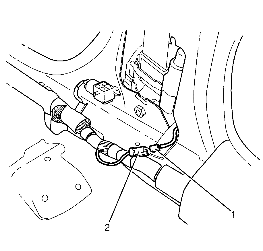
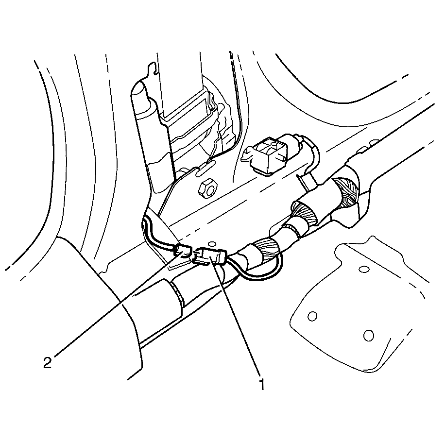
- Disconnect the steering wheel module yellow connector (2) from vehicle harness yellow connector (1).
- If vehicle is equipped with dual stage air bag the steering wheel module and I/P module will each have 4 wires. Refer to Component Connector End Views , for determining high and low circuits.
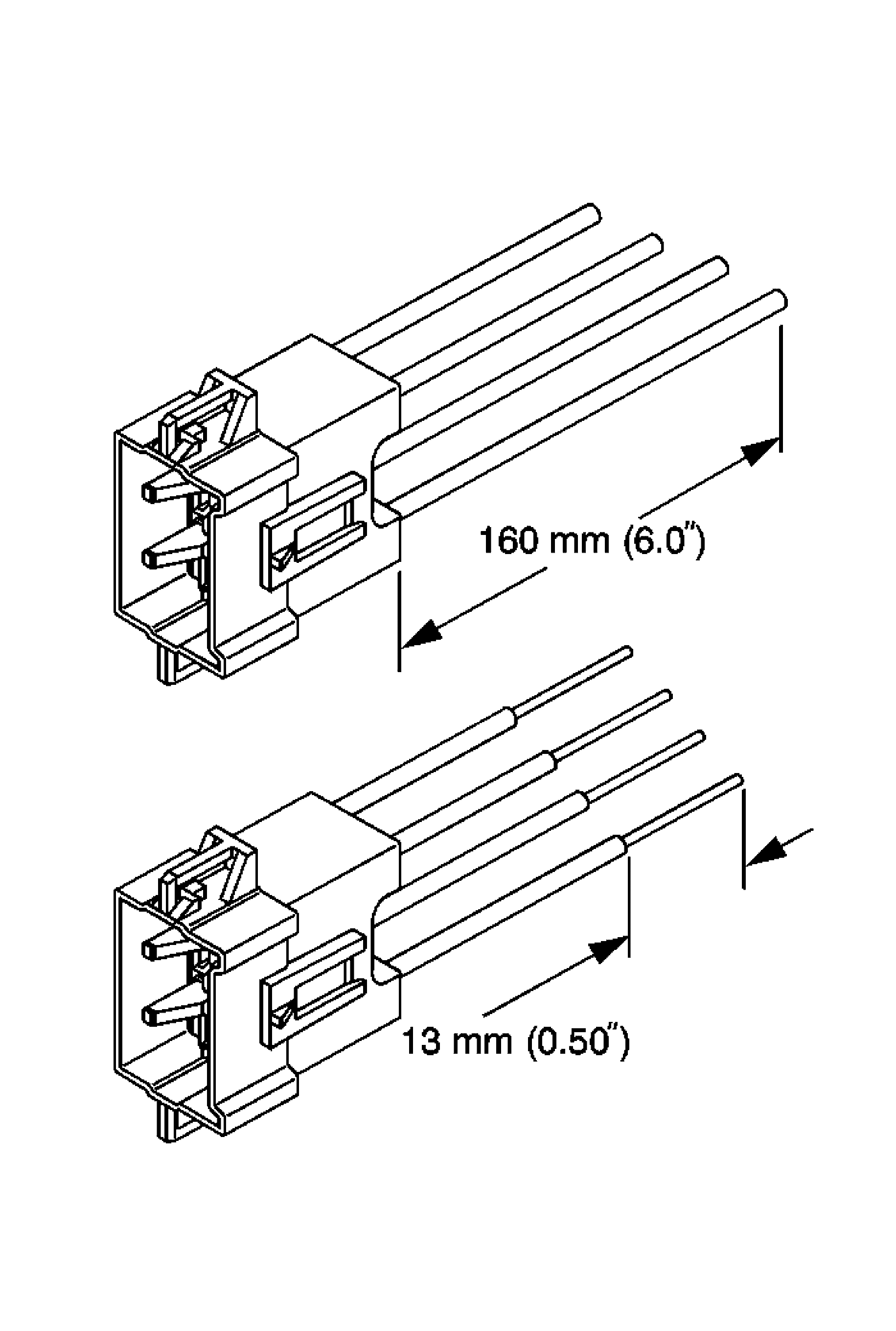
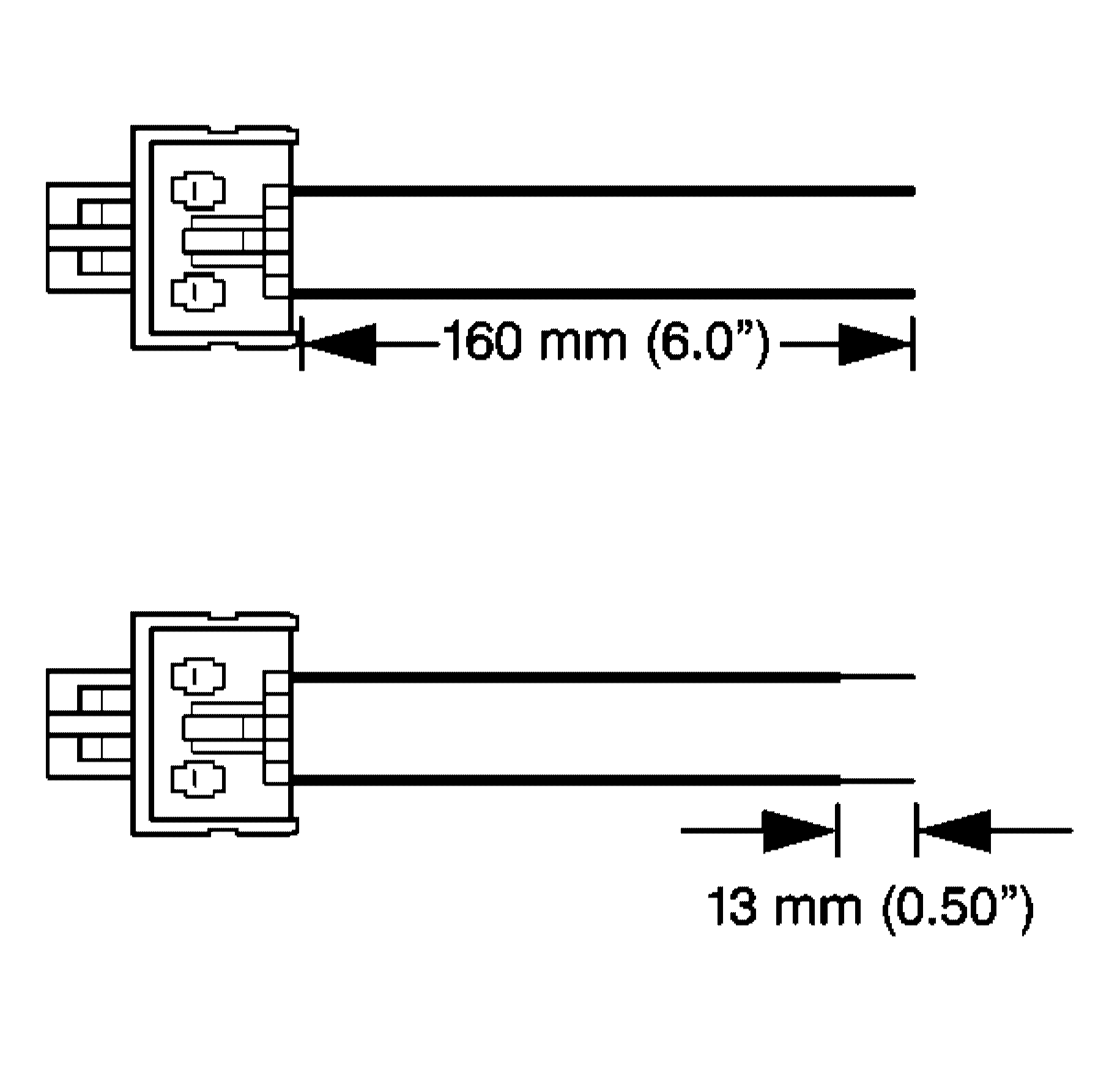
- Cut the yellow vehicle harness connector (1) out of the vehicle, leaving at least 16 cm (6 in) of wire at the connector.
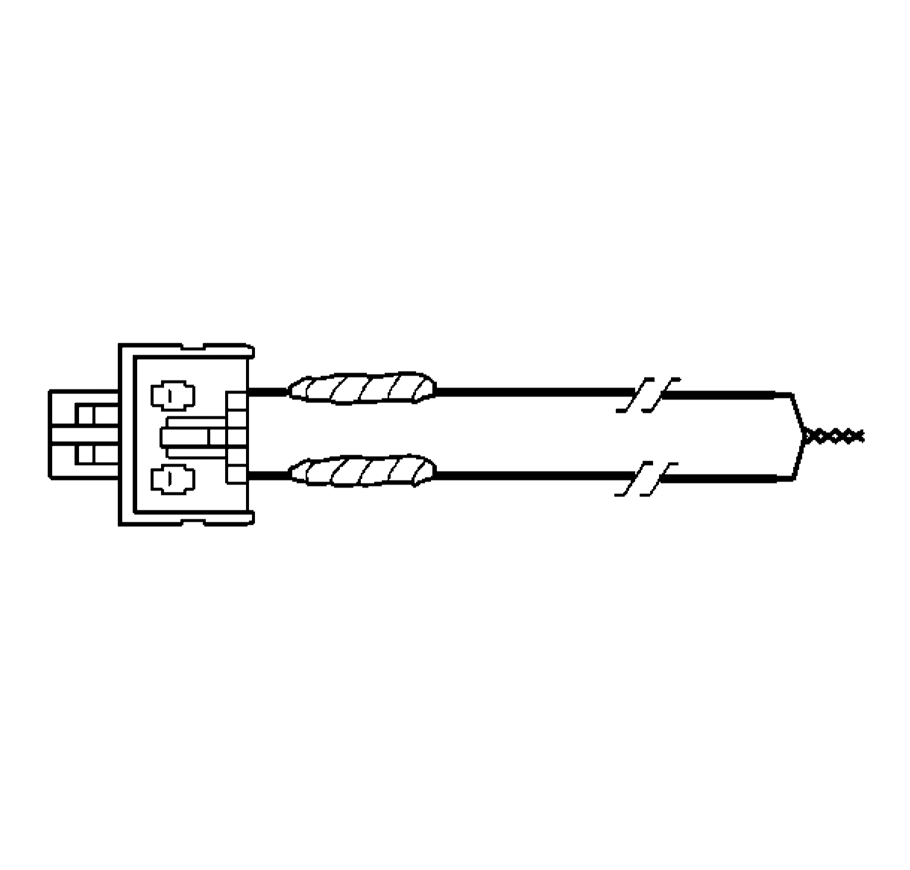
- Strip 13 mm (0.5 in) of insulation from each of the connector wire leads.
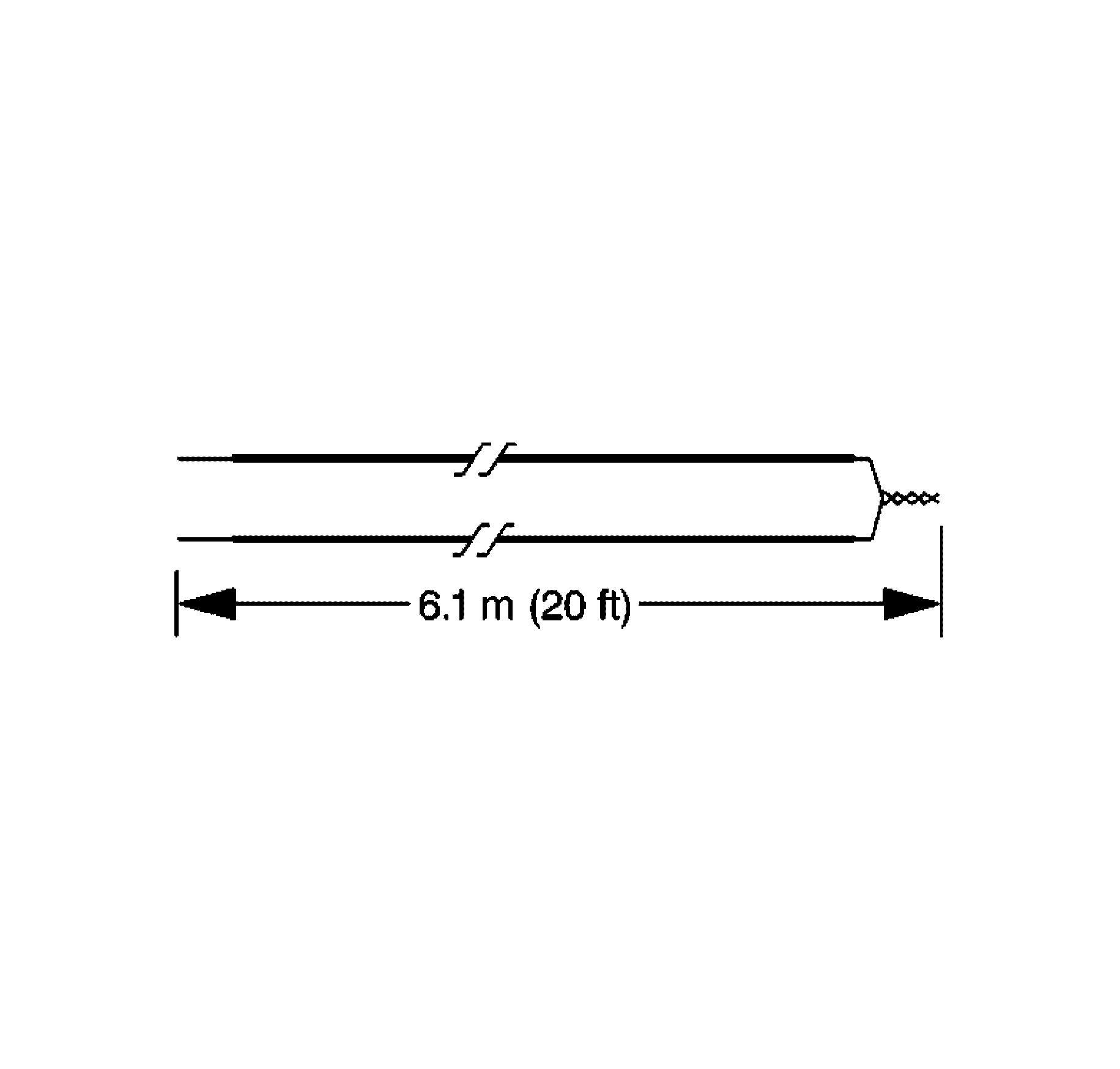
- Cut two 6.1 m (20 ft) deployment wires from a 0.8 mm (18 gage) or thicker multi-strand wire. Use these wires to fabricate the driver deployment harness.
- Strip 13 mm (0.5 in) of insulation from both ends of the wires cut in the previous step.
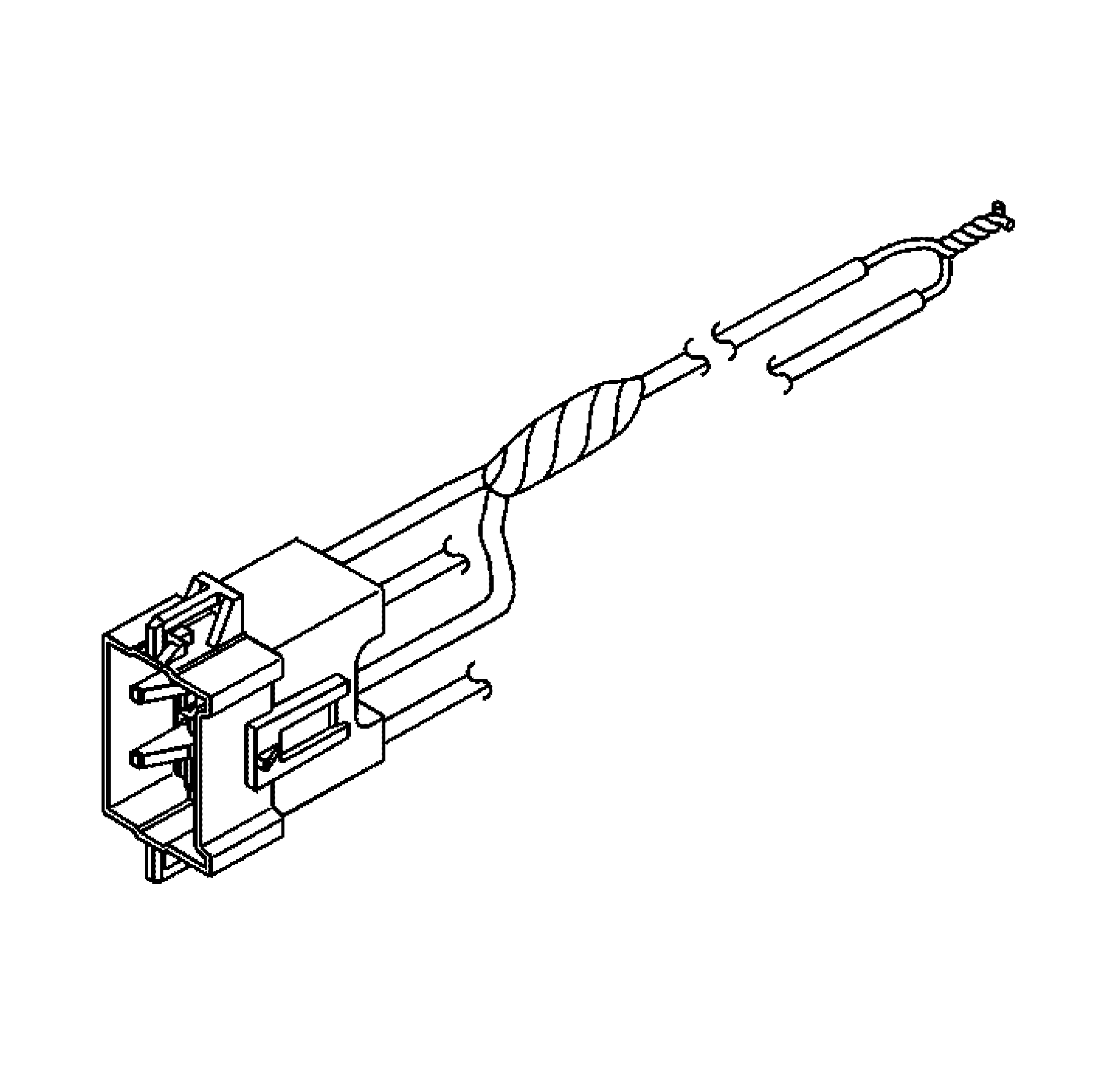
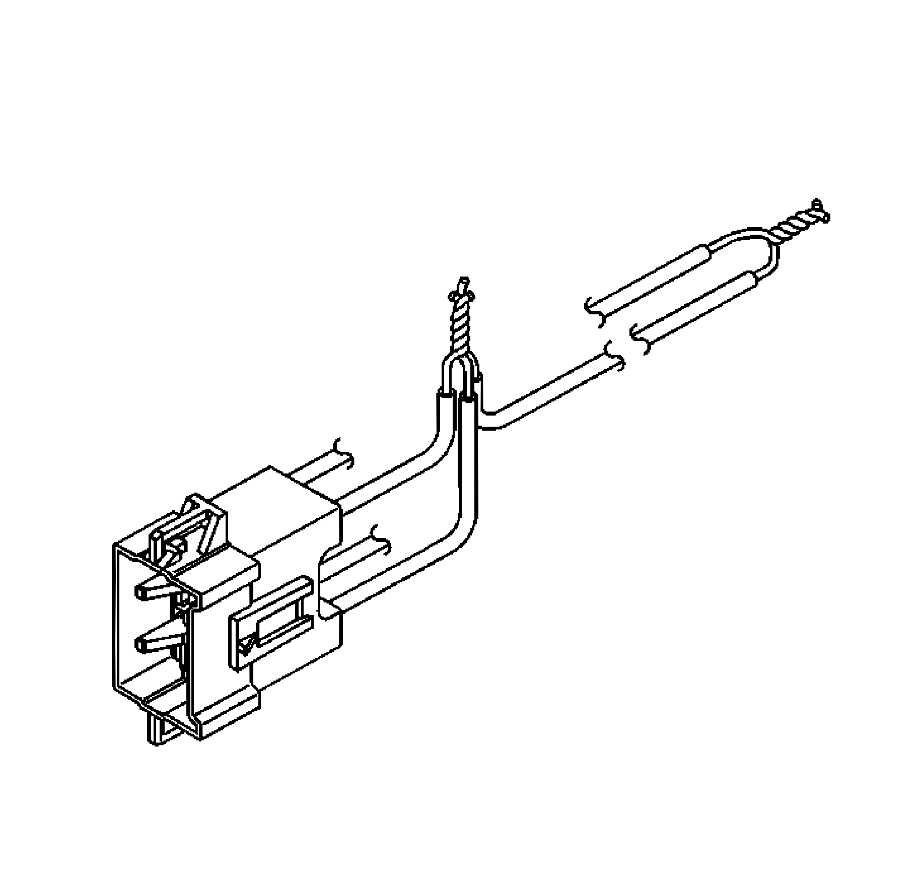
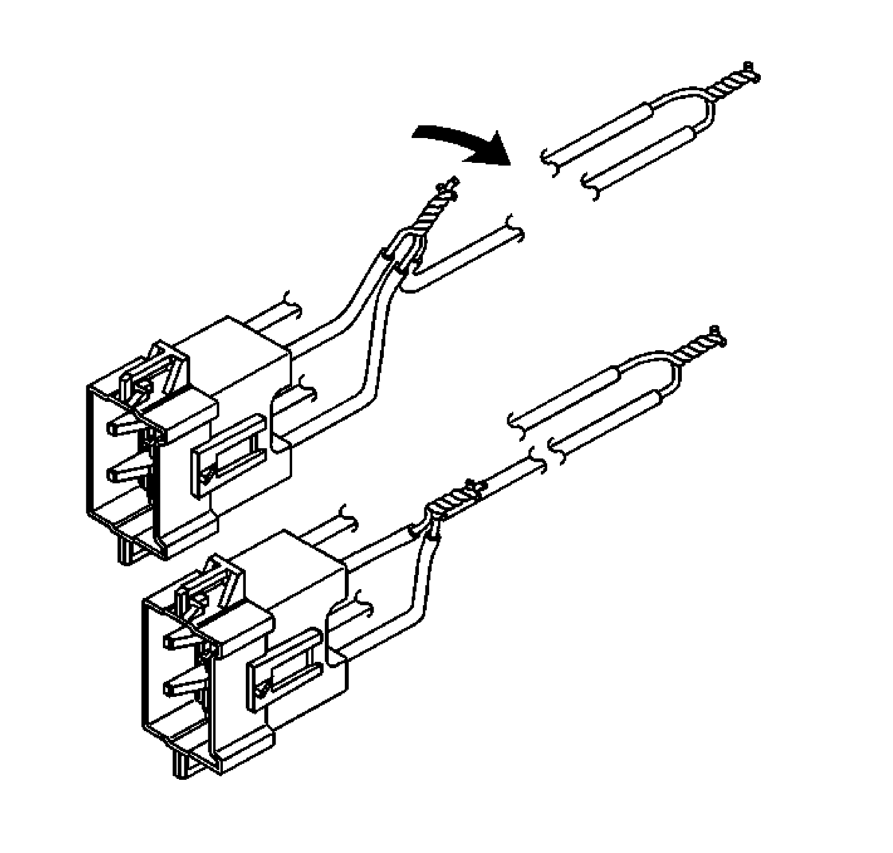
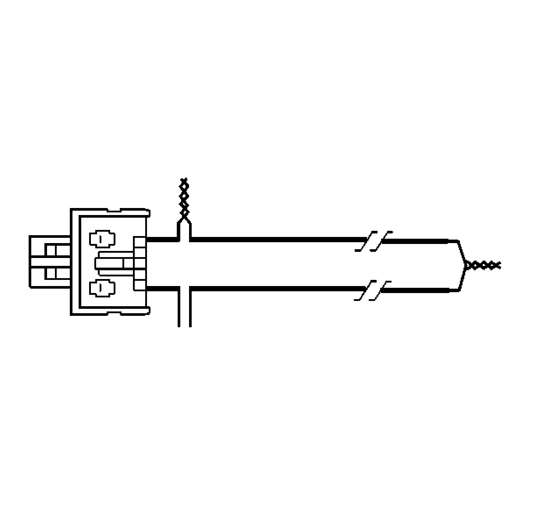
- Twist together one end from each of the wires in order to short the wires. Deployment wires shall remain shorted and not connected to a power source until you are ready to deploy the inflator module.
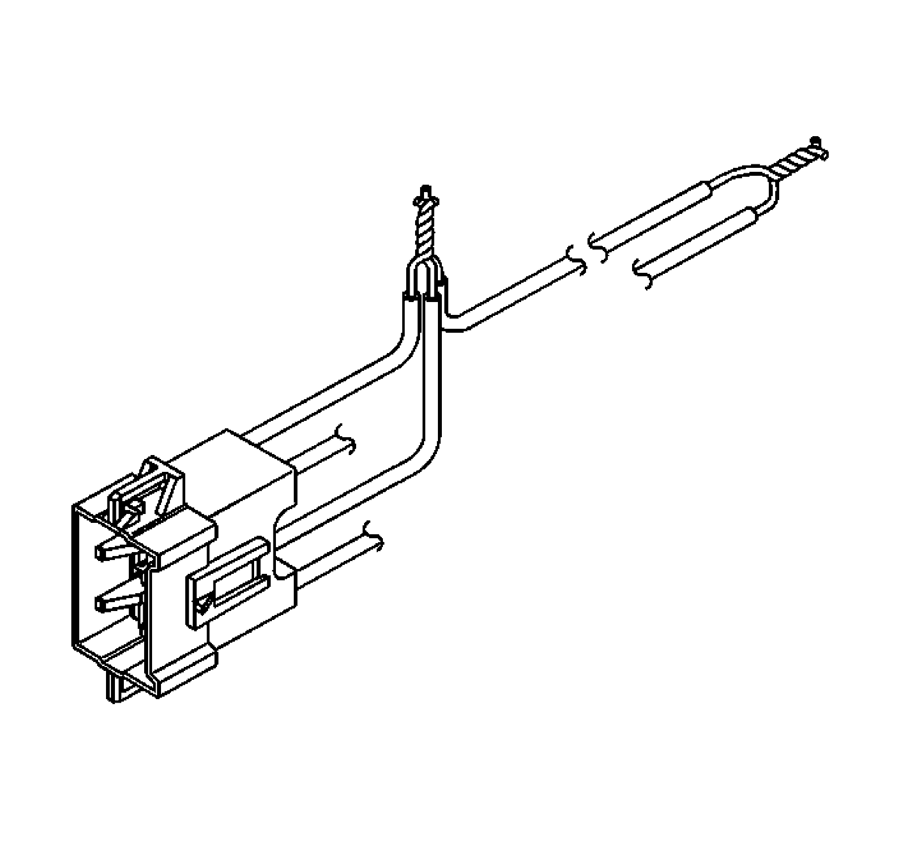
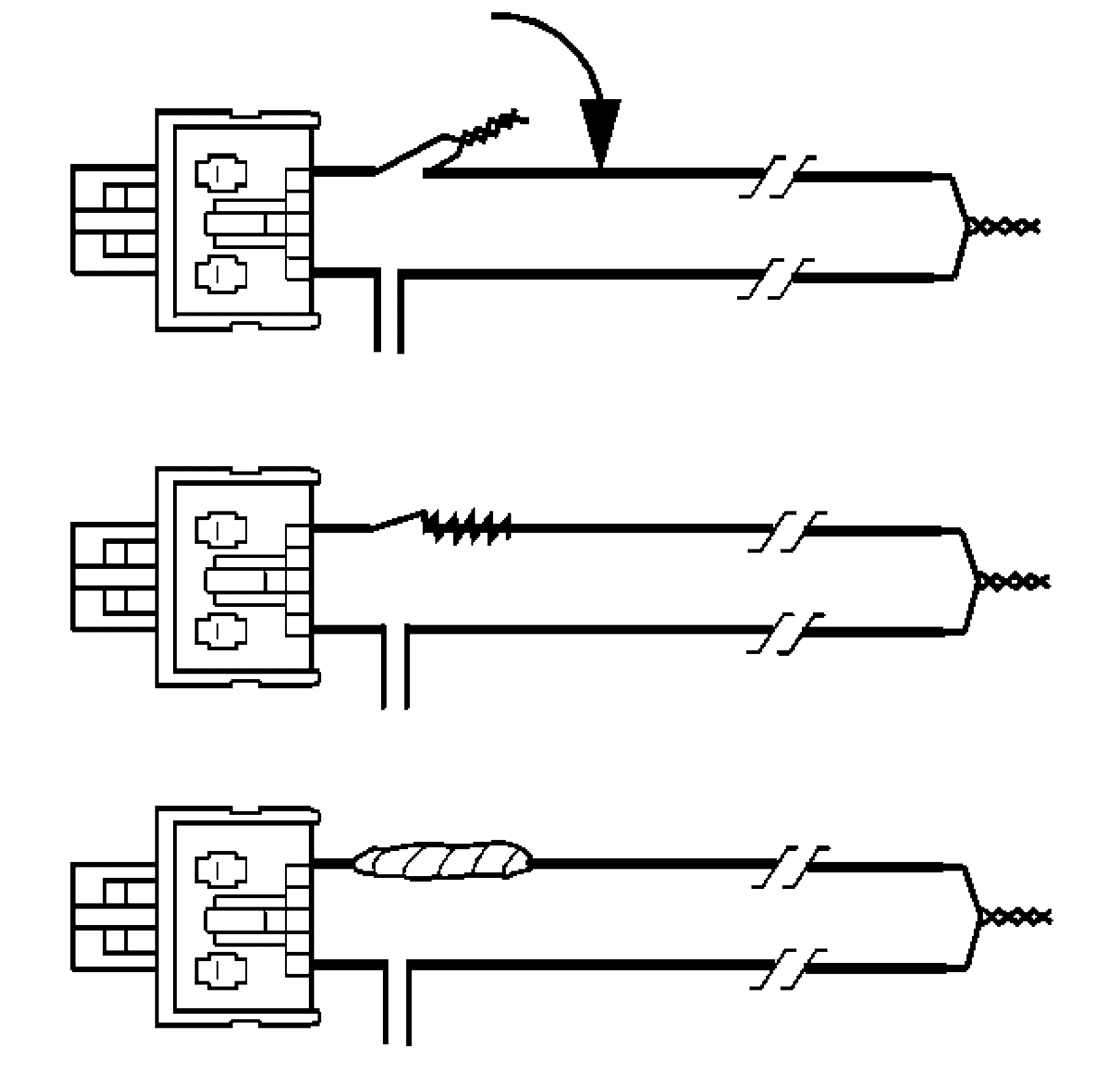
- Twist together 2 connector wire leads (the high circuits from both stages of the steering wheel module) to one sets of deployment wires. Refer to Component Connector End Views , in order to determine the correct circuits.
- Inspect that the 3-wire connection is secure.
- Bend flat the twisted connection.
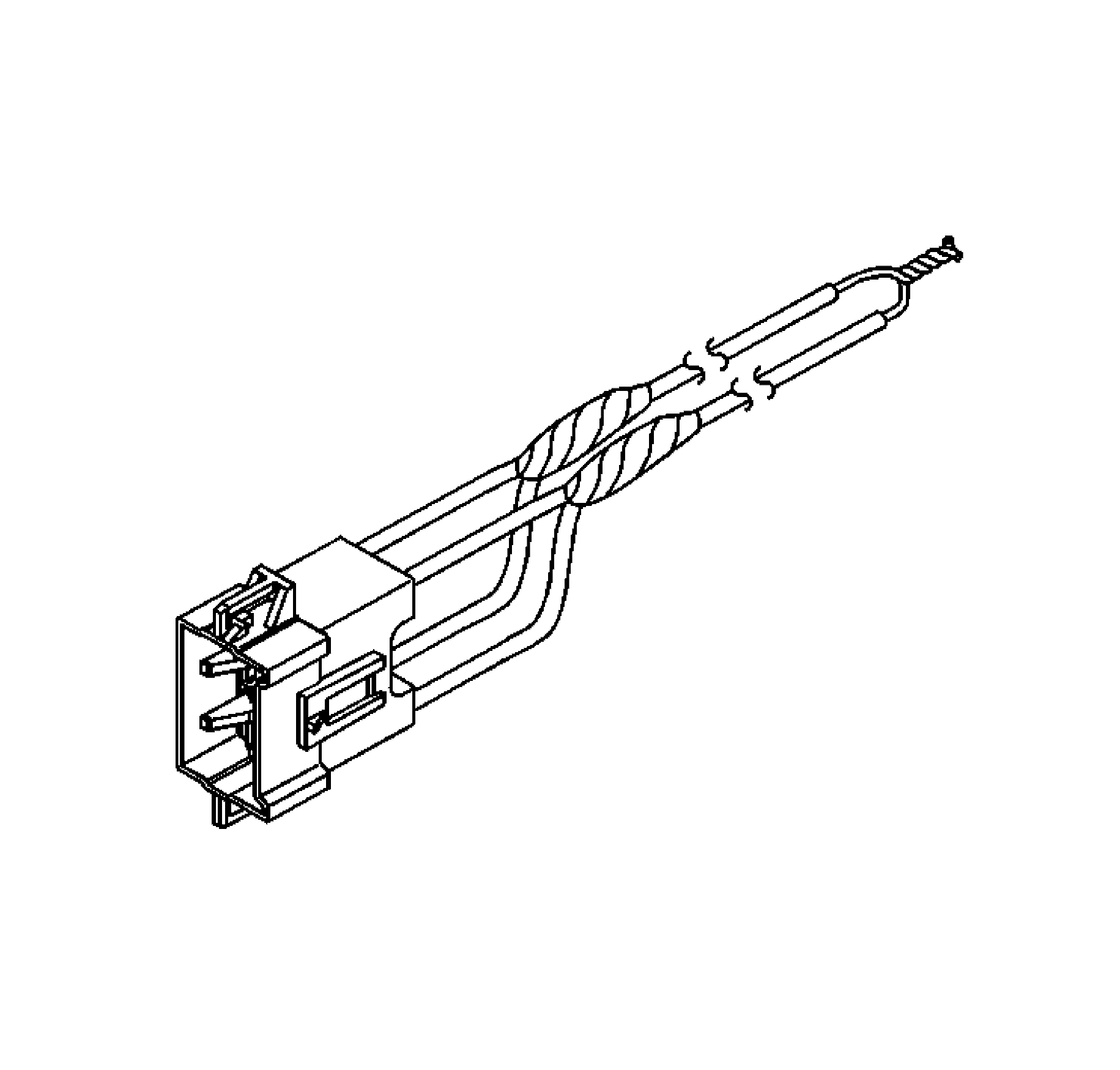
- Secure and insulate the 3-wire connection to deployment harness using electrical tape.
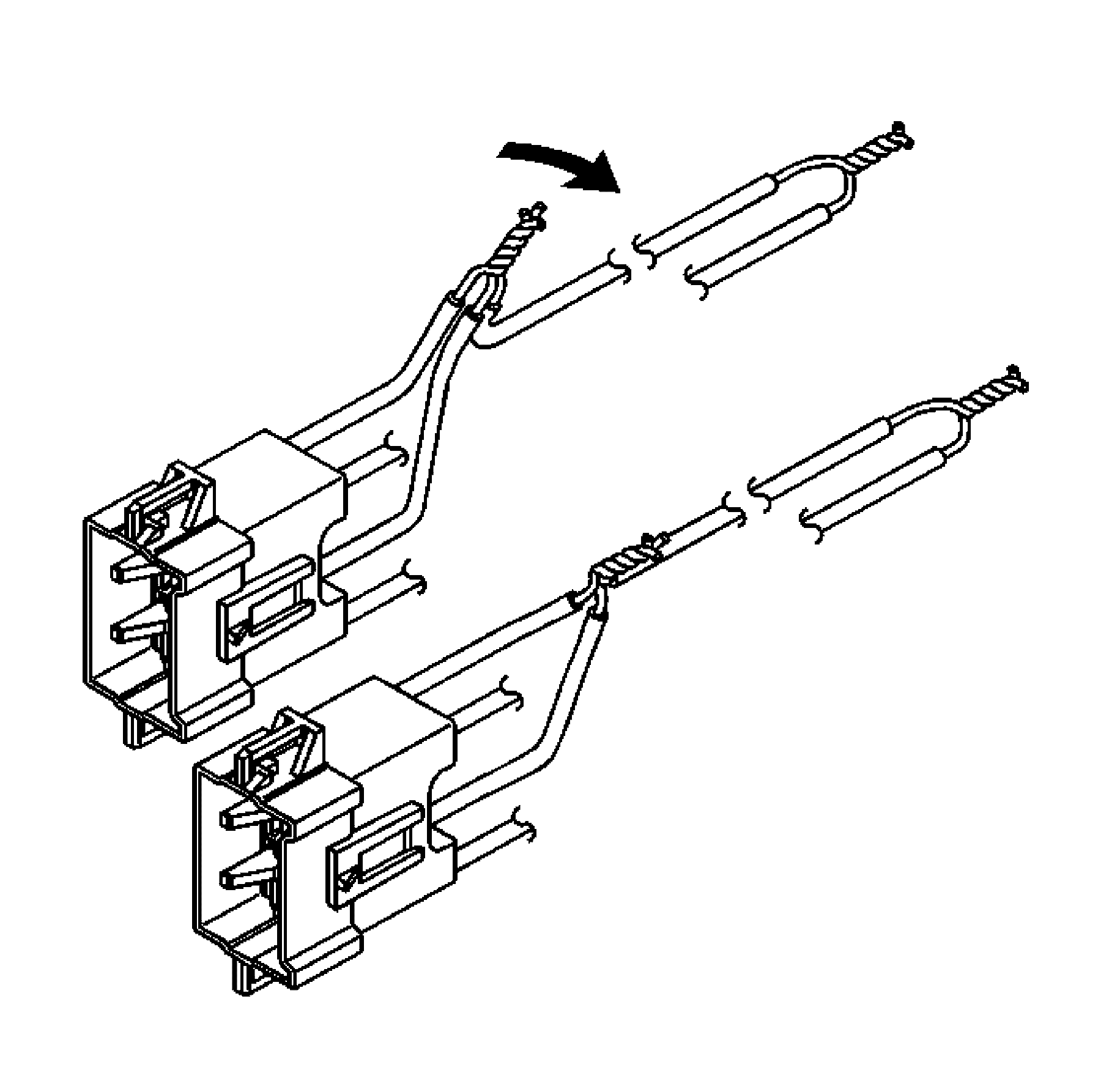
- Twist together 2 connector wire leads (the low circuits from both stages of the steering wheel module) to one sets of deployment wires. Refer to Component Connector End Views , in order to determine the correct circuits.
- Inspect that the 3-wire connection is secure.
- Bend flat the twisted connection.
- Secure and insulate the 3-wire connection to deployment harness using electrical tape.
- Connect the deployment harness to the steering wheel module in-line connector.
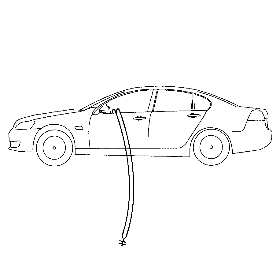
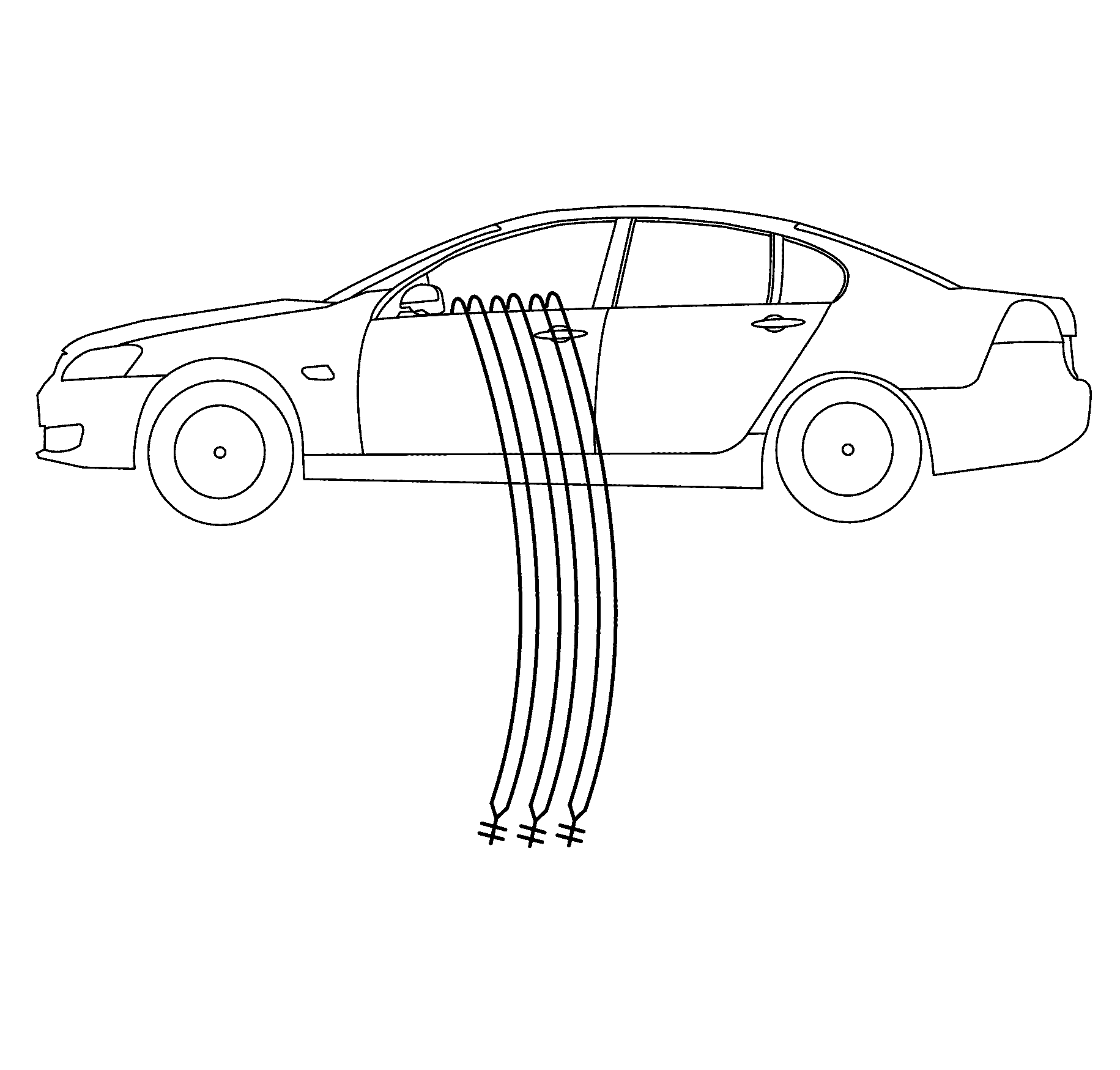
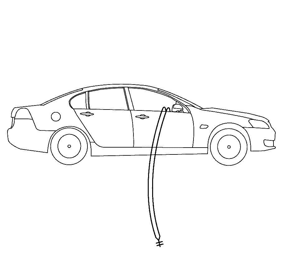
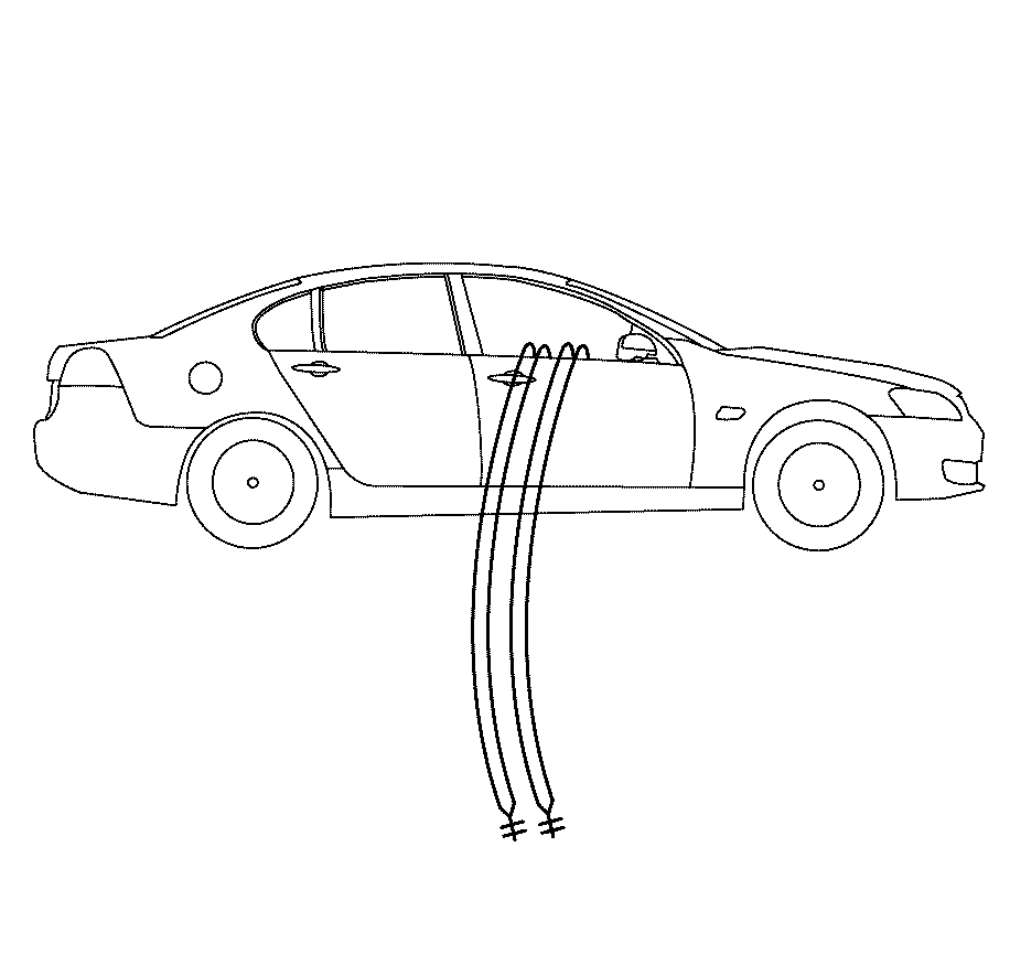
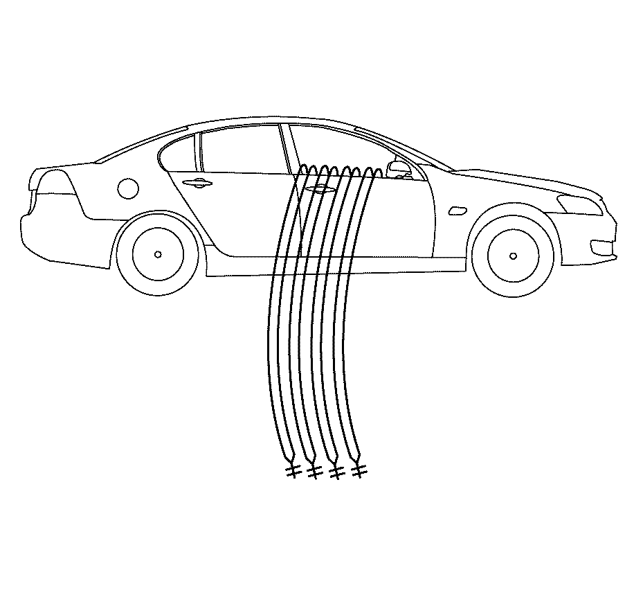
- Route the deployment harness out of the driver side of the vehicle.
- Remove the front seat outer rear adjuster cover. Refer to Driver or Passenger Seat Outer Adjuster Rear Finish Cover Replacement.
- Remove the front seat outer front adjuster cover. Refer to Driver or Passenger Seat Outer Adjuster Front Finish Cover Replacement.
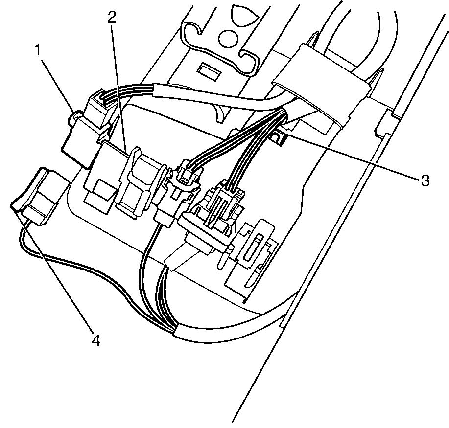
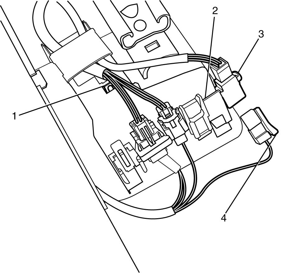
- Detach the connector housing assembly (3) from the floor panel.
- Detach the driver side air bag/pretensioner yellow connector (1 and 4) from the connector housing assembly (2).
- Disconnect the driver side air bag/pretensioner yellow connector (1) from the vehicle harness yellow connector (4).
- Cut the yellow harness connector wires (2 for side air bag and 2 for pretensioner) leading to the yellow harness connector (4) from the vehicle, leaving at least 16 cm (6 in) of wire at the connector.
- Strip 13 mm (0.5 in) of insulation from all 4 SIR wires connector leads (2 for side air bag and 2 for pretensioner).
- Cut two 6.1 m (20 ft) deployment wires from a 0.8 mm (18 gage) or thicker multi-strand wire. Use these wires to fabricate the deployment harness.
- Strip 13 mm (0.5 in) of insulation from both ends of the wires cut in the previous step.
- Twist together one end from each of the wires in order to short the wires. Deployment wires shall remain shorted, and not connected to a power source until you are ready to deploy the side air bag module and pretensioner.
- Twist together 2 connector wire leads (the high circuits from side air bag and pretensioner ) to one sets of deployment wires. Refer to Component Connector End Views SIR Connector End Views in SIR, in order to determine the correct circuits.
- Inspect that the 3-wire connection is secure.
- Bend flat the twisted connection.
- Secure and insulate the 3-wire connection to deployment harness using electrical tape.
- Twist together 2 connector wire leads (the low circuits from side air bag and pretensioner ) to one sets of deployment wires. Refer to Component Connector End Views SIR Connector End Views in SIR, in order to determine the correct circuits.
- Inspect that the 3-wire connection is secure.
- Bend flat the twisted connection.
- Secure and insulate the 3-wire connection to deployment harness using electrical tape.
- Connect the deployment harness to the driver side air bag/pretensioner yellow connector.
- Route the deployment harness out of the driver side of the vehicle.
- Remove the door sill trim plate. Refer to Door Sill Plate Replacement.
- Remove the lower centre pillar trim plate. Refer to Center Pillar Lower Trim Panel Replacement.
- Disconnect the driver side seat belt retractor pretensioner connector (1) from the vehicle harness connector (4).
- Cut the harness connector leading to the harness connector (4) from the vehicle, leaving at least 16 cm (6 in) of wire at the connector.
- Strip 13 mm (0.5 in) of insulation from each of the connector wire leads.
- Cut two 6.1 m (20 ft) deployment wires from a 0.8 mm (18 gage) or thicker multi-strand wire. These wires will be used to fabricate the seat belt retractor pretensioner deployment harness.
- Strip 13 mm (0.5 in) of insulation from both ends of the wires cut in the previous step.
- Twist together one end from each of the wires in order to short the wires.
- Twist together one connector wire lead to one deployment wire.
- Bend flat the twisted connection.
- Secure and insulate the connection using electrical tape.
- Twist together, bend, and tape the remaining connector wire lead to the remaining deployment wire.
- Connect the deployment harness to the seat belt retractor pretensioner connector.
- Route the deployment harness out of the driver side of the vehicle.
- Remove the rear shelf trim panel. Refer to Rear Window Shelf Trim Panel Replacement.
- Remove the headliner. Refer to Headlining Trim Panel Replacement.
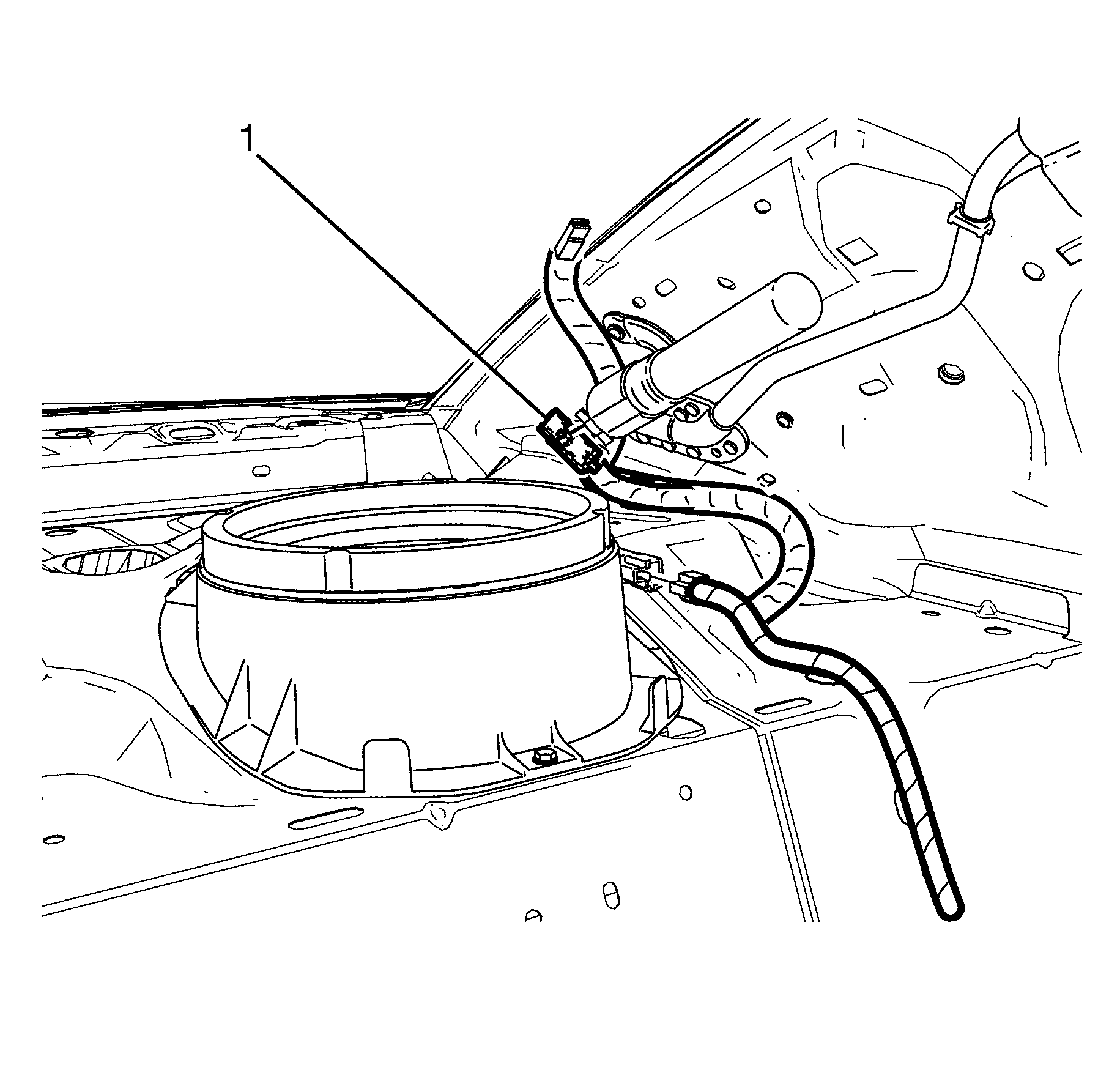
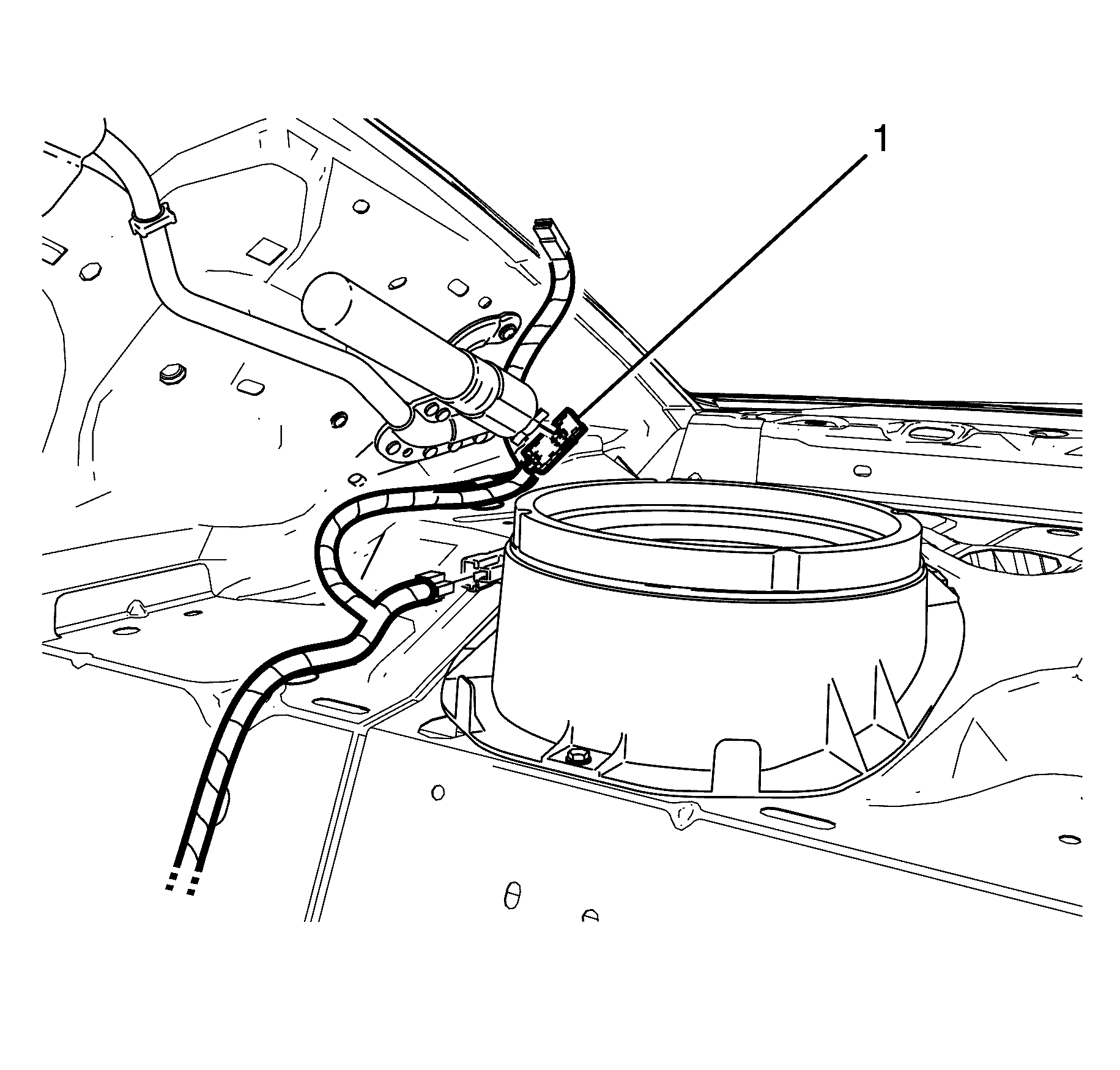
- Disconnect the left/driver roof rail yellow harness connector (1) from the left roof rail air bag.
- Cut the harness connector out of the vehicle, leaving at least 16 cm (6 in) of wire at the connector.
- Strip 13 mm (0.5 in) of insulation from each of the connector wire leads.
- Cut two 6.1 m (20 ft) deployment wires from a 0.8 mm (18 gage) or thicker multi-strand wire. These wires will be used to fabricate the roof rail air bag deployment harness.
- Strip 13 mm (0.5 in) of insulation from both ends of the wires cut in the previous step.
- Twist together one end from each of the wires in order to short the wires.
- Twist together one connector wire lead to one deployment wire.
- Bend flat the twisted connection.
- Secure and insulate the connection using electrical tape.
- Twist together, bend, and tape the remaining connector wire lead to the remaining deployment wire.
- Connect the deployment harness to the roof rail module yellow connector.
- Route the deployment harness out of the driver side of the vehicle.
- Remove the close out panel. Refer to Instrument Panel Insulator Panel Replacement - Left Side.
- Remove the I/P compartment. Refer to Instrument Panel Compartment Replacement.
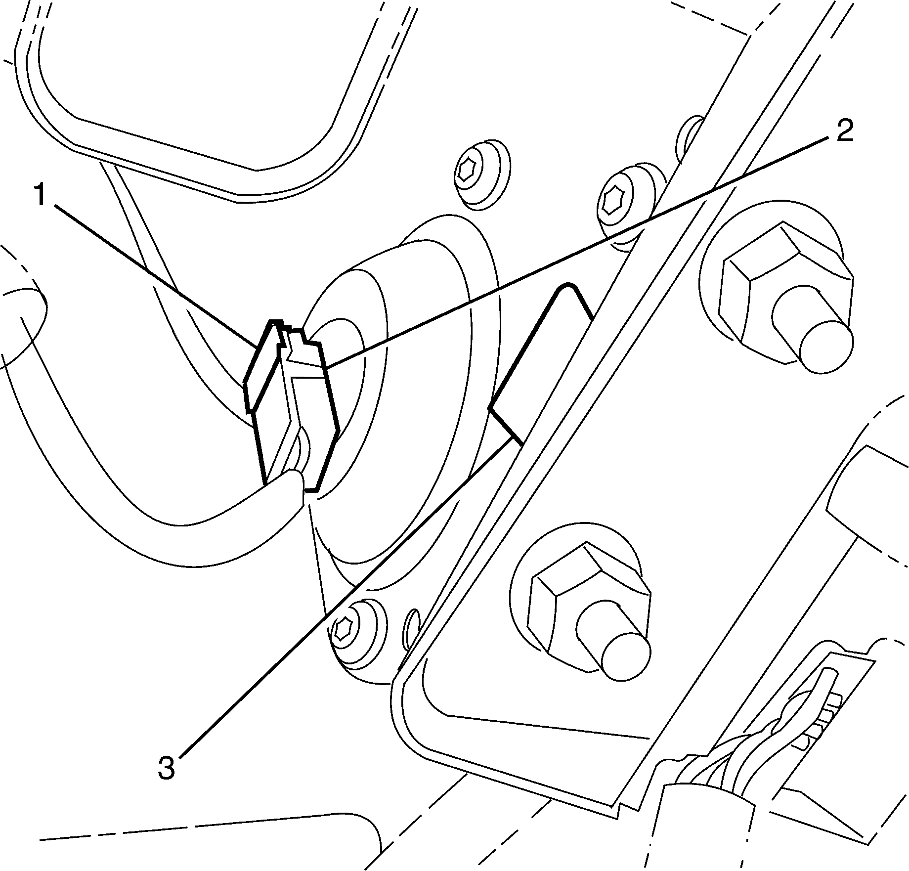
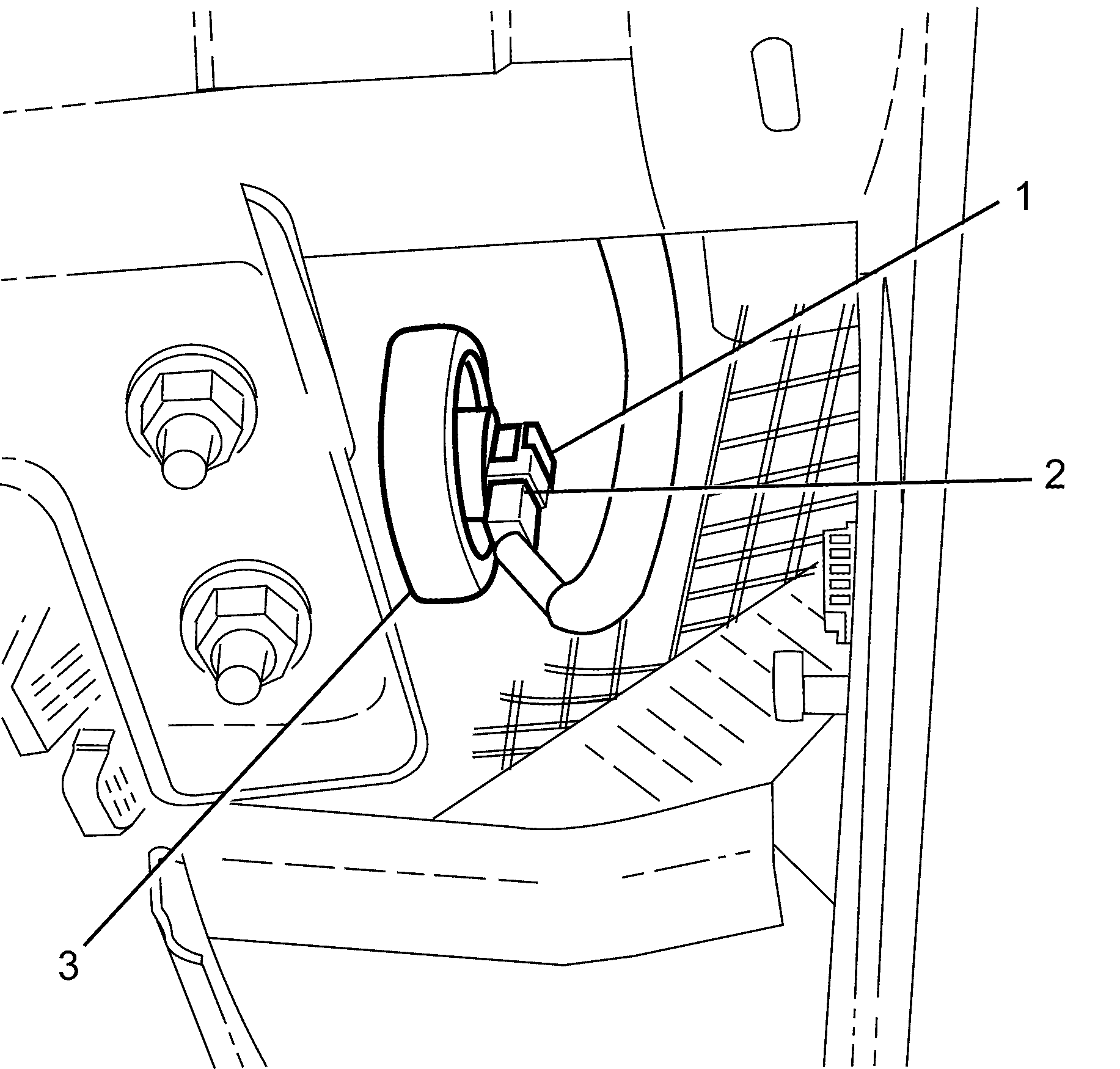
- Release the electrical connector retaining clip (1) and disconnect the electrical connector (2) from the air bag (3).
- Release the electrical connector retaining clip (1) and disconnect the electrical connector (2) from the air bag (3).
- If vehicle is equipped with dual stage air bags the I/P module will each have 4 wires. Refer to Component Connector End Views , for determining high and low circuits.
- Cut the yellow harness connector out of the vehicle, leaving at least 16 cm (6 in) of wire at the connector.
- Strip 13 mm (0.5 in) of insulation from each of the connector wire leads.
- Cut two 6.1 m (20 ft) deployment wires from a 0.8 mm (18 gage) or thicker multi-strand wire. These wires will be used to fabricate the passenger deployment harness.
- Strip 13 mm (0.5 in) of insulation from both ends of the wires cut in the previous step.
- Twist together one end from each of the wires in order to short the wires.
- Twist together 2 connector wire leads (the high circuits from both stages of the steering wheel module) to one sets of deployment wires. Refer to Component Connector End Views , in order to determine the correct circuits.
- Inspect that the 3-wire connection is secure.
- Bend flat the twisted connection.
- Secure and insulate the 3-wire connection to deployment harness using electrical tape.
- Twist together 2 connector wire leads (the low circuits from both stages of the I/P module) to one sets of deployment wires. Refer to Component Connector End Views , in order to determine the correct circuits.
- Inspect that the 3-wire connection is secure.
- Bend flat the twisted connection.
- Secure and insulate the 3-wire connection to deployment harness using electrical tape.
- Connect the deployment harness to the I/P module in-line connector.
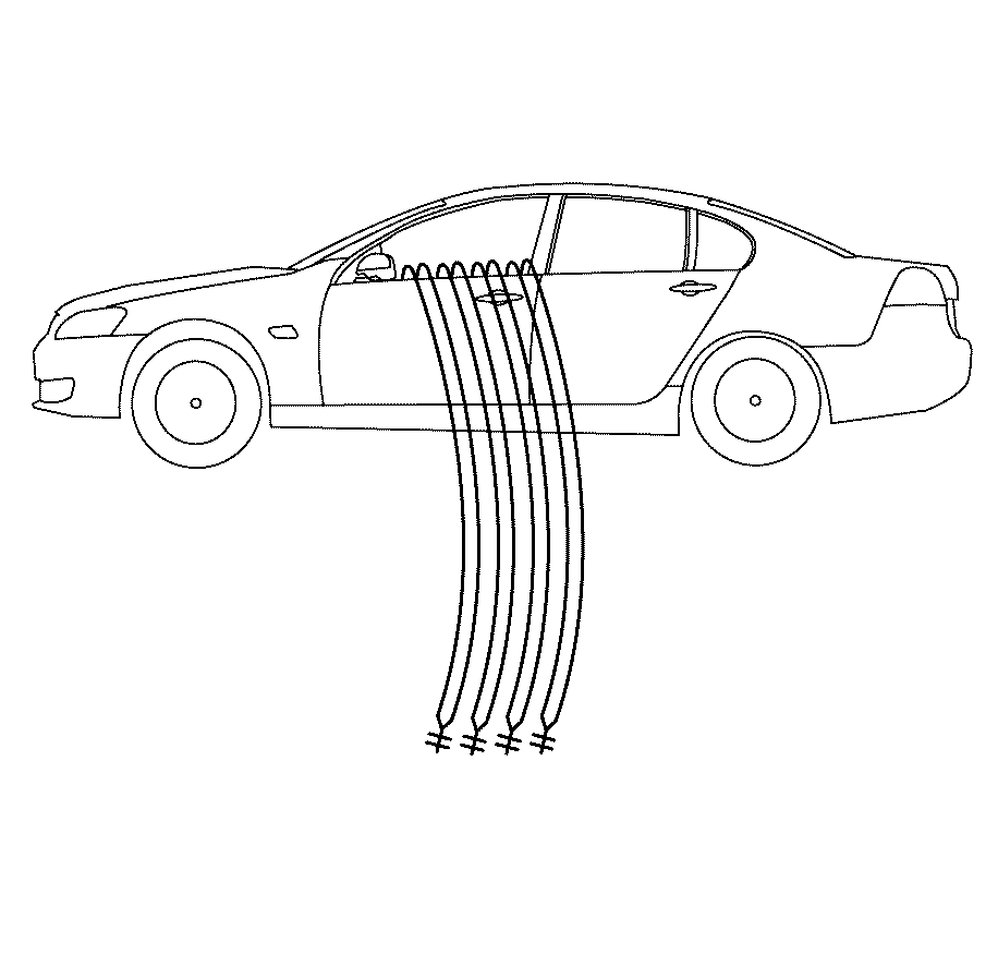
- Route the deployment harness out of the passenger side of the vehicle.
- Remove the front seat outer rear adjuster cover. Refer to Driver or Passenger Seat Outer Adjuster Rear Finish Cover Replacement.
- Remove the front seat outer front adjuster cover. Refer to Driver or Passenger Seat Outer Adjuster Front Finish Cover Replacement.
- Detach the connector housing assembly (1) from the floor panel.
- Detach the passenger side air bag/pretensioner yellow connector (3 and 4) from the connector housing assembly (2).
- Disconnect the passenger side air bag/pretensioner yellow connector (3) from the vehicle harness yellow connector (4).
- Cut the yellow harness connector wires (2 for side air bag and 2 for pretensioner) leading to the yellow harness connector (4) from the vehicle, leaving at least 16 cm (6 in) of wire at the connector.
- Strip 13 mm (0.5 in) of insulation from all 4 SIR wires connector leads (2 for side air bag and 2 for pretensioner).
- Cut two 6.1 m (20 ft) deployment wires from a 0.8 mm (18 gage) or thicker multi-strand wire. Use these wires to fabricate the deployment harness.
- Strip 13 mm (0.5 in) of insulation from both ends of the wires cut in the previous step.
- Twist together one end from each of the wires in order to short the wires. Deployment wires shall remain shorted, and not connected to a power source until you are ready to deploy the side air bag module and pretensioner.
- Twist together 2 connector wire leads (the high circuits from side air bag and pretensioner) to one sets of deployment wires. Refer to Component Connector End Views , in order to determine the correct circuits.
- Inspect that the 3-wire connection is secure.
- Bend flat the twisted connection.
- Secure and insulate the 3-wire connection to deployment harness using electrical tape.
- Twist together 2 connector wire leads (the low circuits from side air bag and pretensioner) to one sets of deployment wires. Refer to Component Connector End Views , in order to determine the correct circuits.
- Inspect that the 3-wire connection is secure.
- Bend flat the twisted connection.
- Secure and insulate the 3-wire connection to deployment harness using electrical tape.
- Connect the deployment harness to the passenger side air bag/pretensioner yellow connector.
- Route the deployment harness out of the passenger side of the vehicle.
- Disconnect the driver side seat belt retractor pretensioner connector (1) from the vehicle harness connector (4).
- Cut the harness connector leading to the harness connector (4) from the vehicle, leaving at least 16 cm (6 in) of wire at the connector.
- Strip 13 mm (0.5 in) of insulation from each of the connector wire leads.
- Cut two 6.1 m (20 ft) deployment wires from a 0.8 mm (18 gage) or thicker multi-strand wire. These wires will be used to fabricate the seat belt retractor pretensioner deployment harness.
- Strip 13 mm (0.5 in) of insulation from both ends of the wires cut in the previous step.
- Twist together one end from each of the wires in order to short the wires.
- Twist together one connector wire lead to one deployment wire.
- Bend flat the twisted connection.
- Secure and insulate the connection using electrical tape.
- Twist together, bend, and tape the remaining connector wire lead to the remaining deployment wire.
- Connect the deployment harness to the seat belt retractor pretensioner connector.
- Route the deployment harness out of the passenger side of the vehicle.
- Disconnect the right/passenger roof rail yellow harness connector (1) from the right/roof rail air bag.
- Cut the harness connector out of the vehicle, leaving at least 16 cm (6 in) of wire at the connector.
- Strip 13 mm (0.5 in) of insulation from each of the connector wire leads.
- Cut two 6.1 m (20 ft) deployment wires from a 0.8 mm (18 gage) or thicker multi-strand wire. These wires will be used to fabricate the roof rail air bag deployment harness.
- Strip 13 mm (0.5 in) of insulation from both ends of the wires cut in the previous step.
- Twist together one end from each of the wires in order to short the wires.
- Twist together one connector wire lead to one deployment wire.
- Bend flat the twisted connection.
- Secure and insulate the connection using electrical tape.
- Twist together, bend, and tape the remaining connector wire lead to the remaining deployment wire.
- Connect the deployment harness to the roof rail module yellow connector.
- Route the deployment harness out of the passenger side of the vehicle.
- Completely cover the windshield and front door window openings with a drop cloth.
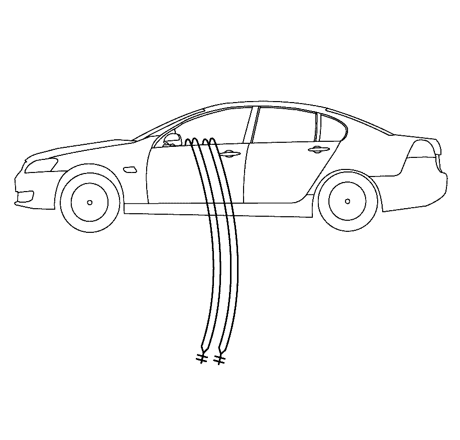
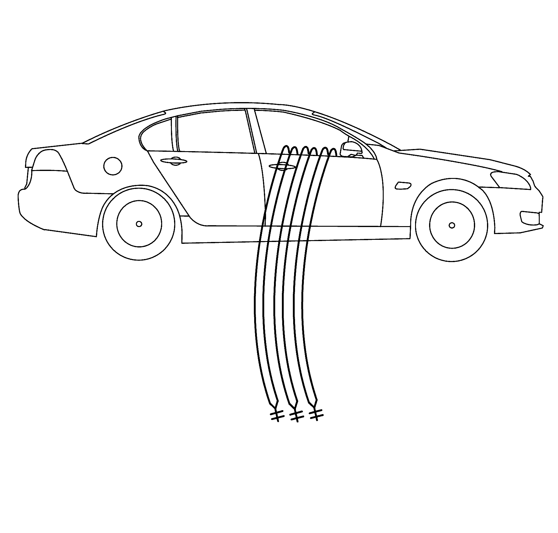
- Stretch out all of the deployment harness wires on the passenger side of the vehicle to their full length.
- Deploy each deployment loop one at a time.
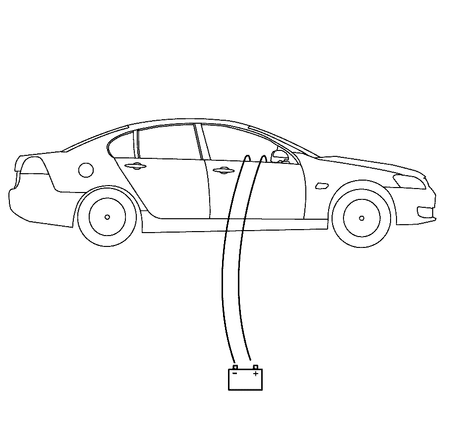
- Place a power source, 12 V minimum/2 A minimum (i.e., a vehicle battery) near the shorted end of the harnesses.
- Separate the one set of wires and touch the wires ends to the power source in order to deploy the inflator modules, doing one module at a time.
- Disconnect the deployment harness from the power source and twist the wire ends together.
- Continue the same process with the remaining deployment harnesses that are available.
- Stretch out all of the deployment harness wires on the driver side of the vehicle to their full length.
- Deploy each deployment loop one at a time.
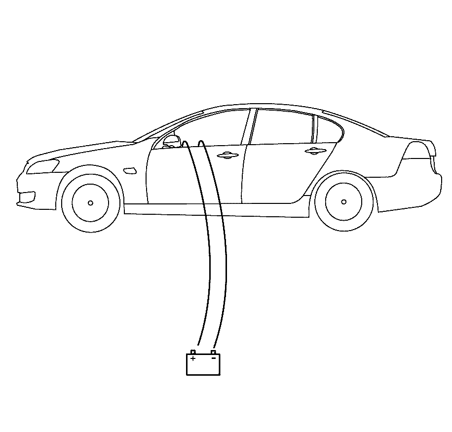
- Place a power source, 12 V minimum/2 A minimum (i.e., a vehicle battery) near the shorted end of the harnesses.
- Separate the one set of wires and touch the wires ends to the power source in order to deploy the inflator modules, doing one module at a time.
- Disconnect the deployment harness from the power source and twist the wire ends together.
- Continue the same process with the remaining deployment harnesses that are available.
- Remove the drop cloth from the vehicle.
- Disconnect all harnesses from the vehicle.
- Discard the harnesses.
- Scrap the vehicle in the same manner as a non-SIR equipped vehicle.
- If one or all of the inflator modules did not deploy, perform the following steps to remove the undeployed module(s) from the vehicle:
Caution: Refer to Safety Glasses Caution in the Preface section.
Important: Deploy the inflator modules inside of the vehicle when destroying the vehicle or when salvaging the vehicle for parts. This includes but is not limited to the following situations:
The vehicle has completed its useful life. Irreparable damage occurs to the vehicle in a non-deployment type accident. Irreparable damage occurs to the vehicle during a theft. The vehicle is being salvaged for parts to be used on a vehicle with a different VIN as opposed to rebuilding as the same VIN.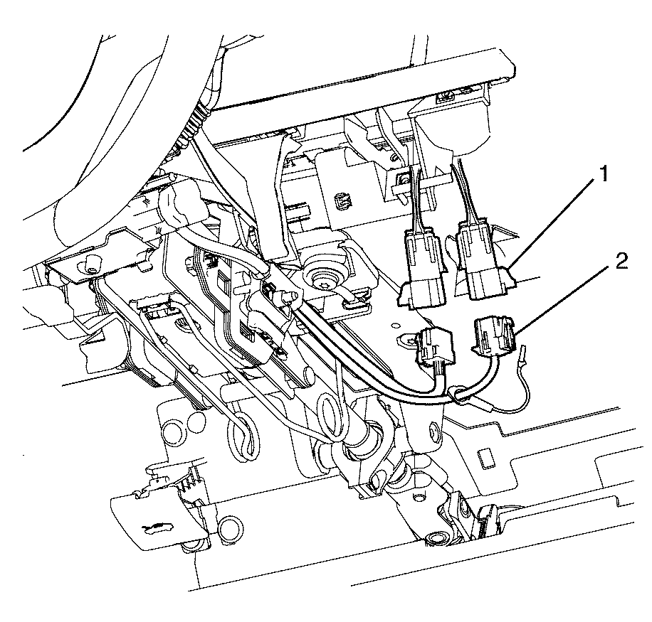













Deployment Procedure - (Out Of Vehicle)
Refer to TAS (Technical Assistant Service) for further instructions.
