Power Steering Pump Replacement ZF
Removal Procedure
- Pump the hydraulic fluid out of the electro-hydraulic supply unit.
- Disconnect the wiring harness from the electro-hydraulic supply unit.
- Remove the lower engine compartment cover.
- Remove the supply and return line from the electro-hydraulic supply unit.
- Remove the electro-hydraulic supply unit with bracket from the front axle body.
Note: The front axle body remains fitted. The electro-hydraulic supply unit of ZF is removed from above with the holder.
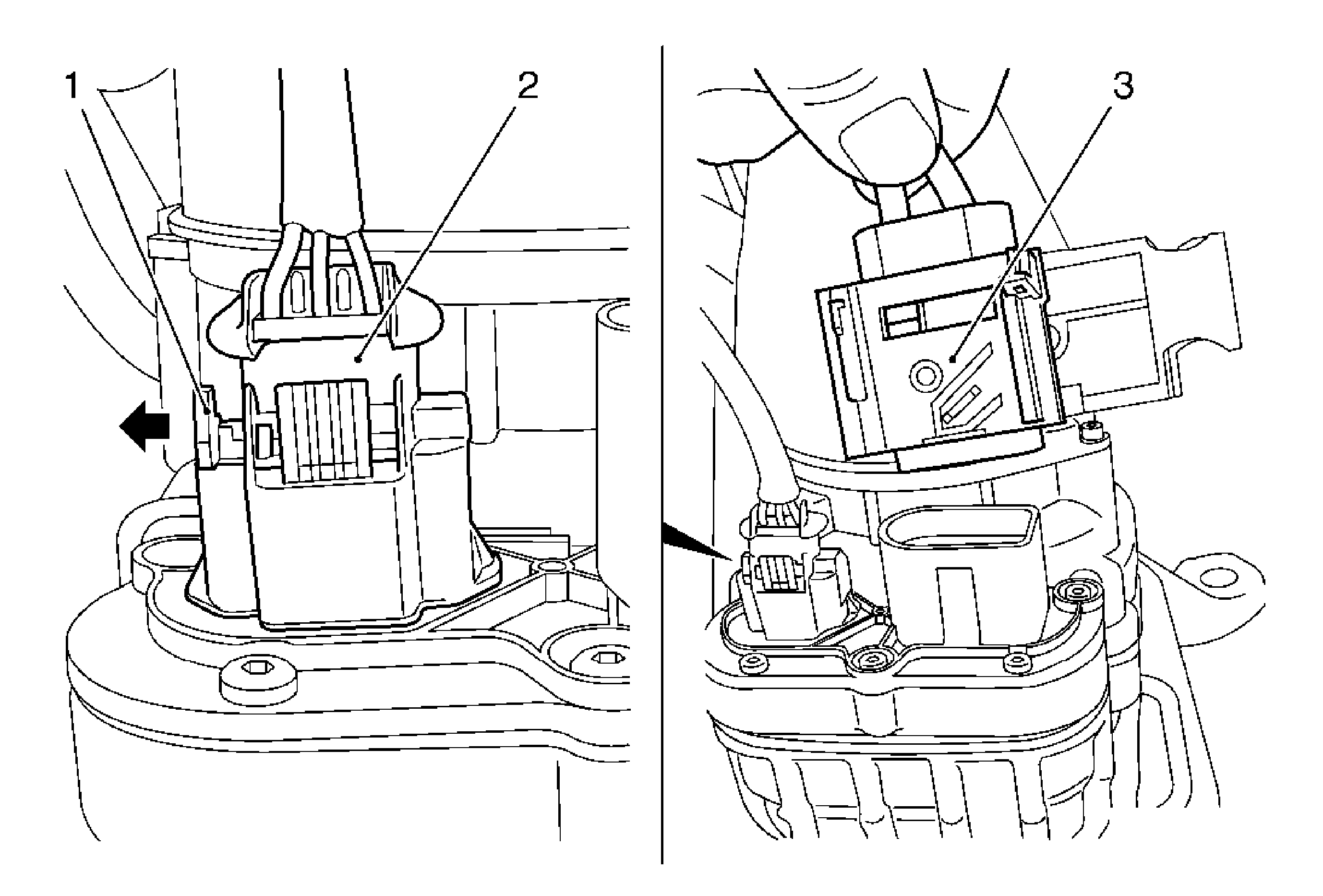
| 2.1. | Unlatch and disconnect the wiring harness plug (3). |
| 2.2. | Release the primary lock (1) from the wiring harness plug. |
| 2.3. | Compress the secondary lock and separate the wiring harness plug (2). |
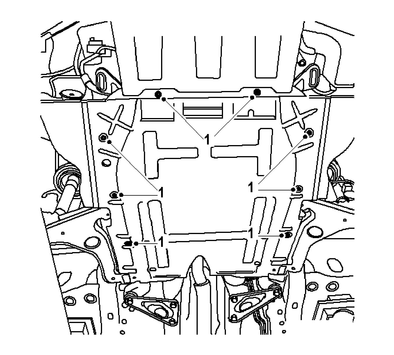
Remove the 10 bolts.
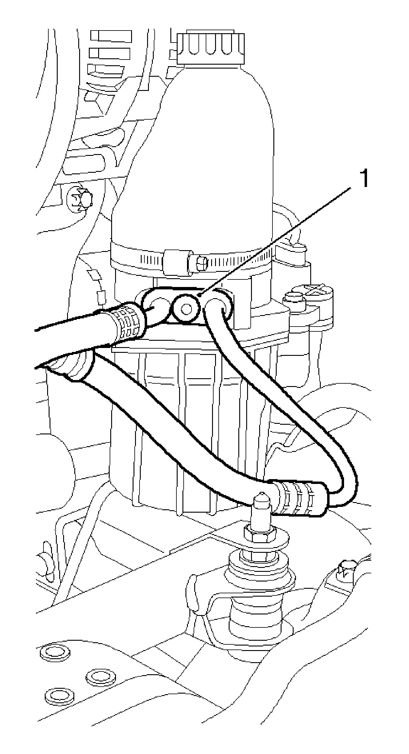
Note: Oil will run out, use a drain pan.
Remove the bolt (1).
Remove the 3 nuts.
Installation Procedure
- Place the electro-hydraulic supply unit with bracket on the front axle body.
- Install the pressure and return lines to the electro-hydraulic supply unit with the new seal rings.
- Connect the wiring harness with the electro-hydraulic supply unit.
- Remove the lower engine compartment cover.
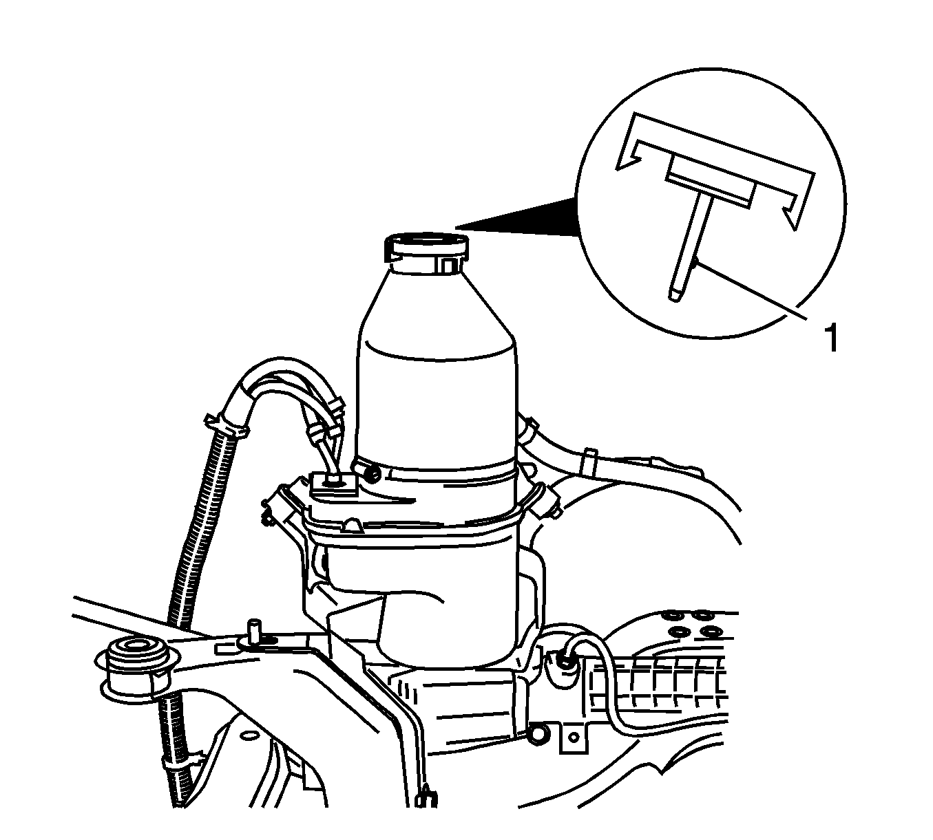
- Add special fluid to the oil tank up to the "MAX" mark (1) on the oil dipstick.
- Place the cover on oil tank and close.
- Bleed the power steering system. Refer to Power Steering System Bleeding.
- For programming procedures, refer to Control Module References.
Caution: Refer to Fastener Caution in the Preface section.
Note: Note the steering wiring harness.
Install the electro-hydraulic supply unit to front axle body.
Tighten
Tighten the 3 nuts to 22 N·m (16 lb ft).

Note: Do not attach the bracket for electro-hydraulic supply unit at this time.
Tighten
Tighten the bolt (1) 16 N·m (12 lb ft).
Connect and lock the 2 wiring harness plugs.

Tighten
Tighten the 10 bolts (1).
Power Steering Pump Replacement TRW
Note: The front frame remains fitted. The electro-hydraulic supply unit of TRW is removed from above without holder.
Removal Procedure
- Remove the battery. Refer to Battery Replacement.
- Remove the battery tray. Refer to Battery Tray Replacement.
- Reposition the surge tank. Refer to Radiator Surge Tank Replacement.
- Disconnect the steering wiring harness.
- Remove the air cleaner housing with the air intake hose.
- Remove the air cleaner assembly. Refer to Air Cleaner Assembly Replacement.
- Remove the bleed hose from the tank bleed valve.
- Remove the right engine splash shield.
- Disconnect the wiring harness for the steering from the front frame.
- Remove the return (1) and supply line (2) from the electro-hydraulic supply unit.
- Remove the electro-hydraulic supply unit from the holder.
- Remove the electro-hydraulic supply unit from the holder.
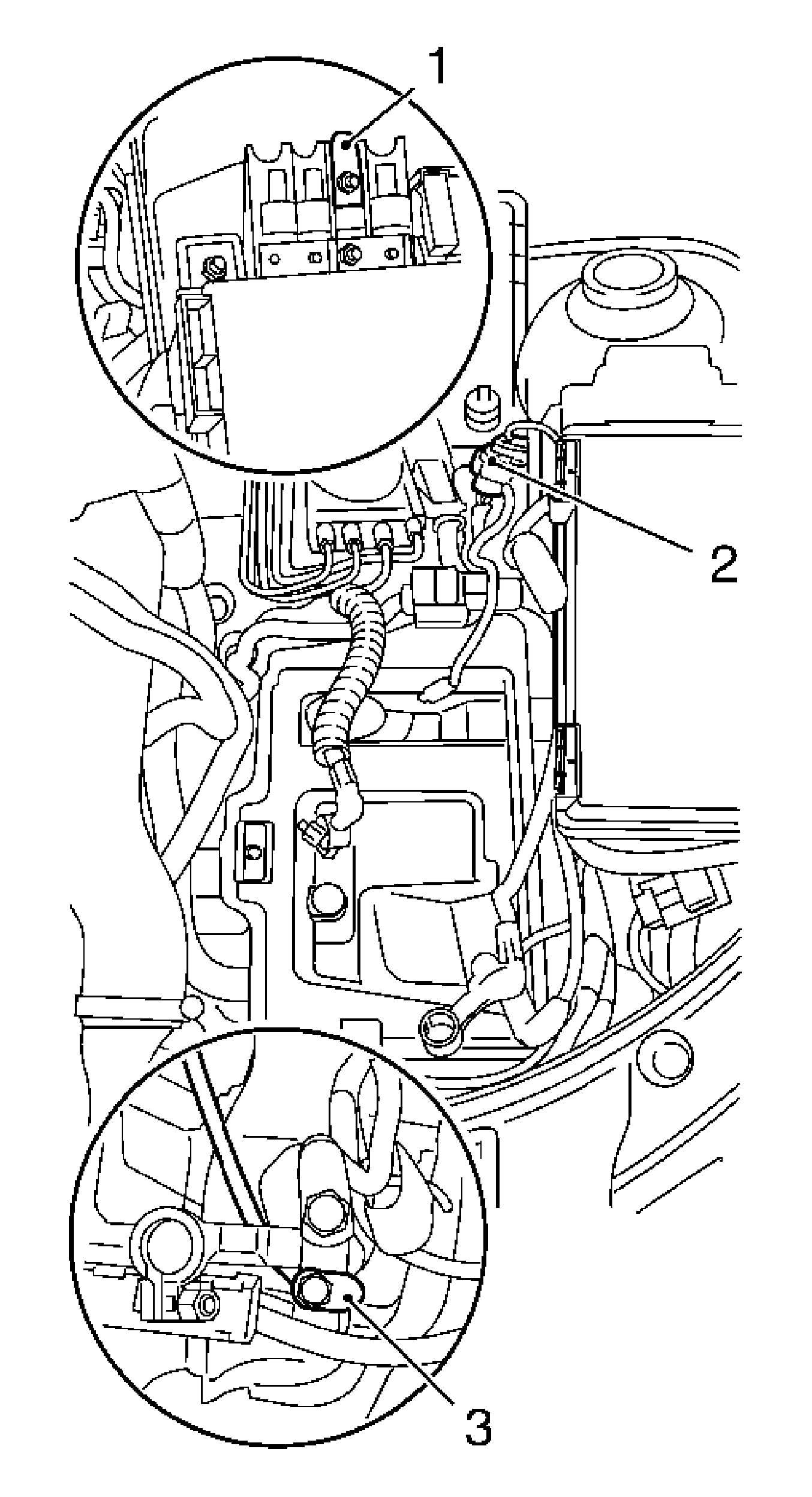
Note: The cooling system remains sealed.
Disconnect the wiring harness plug.
| • | Disconnect the cover from the positive distribution. |
| • | Remove the wiring harness from the fixing (1). |
| • | Disconnect the wiring harness plug for steering (2). |
| • | Disconnect the ground cable (3) for steering wiring harness from ground pole terminal. |
| • | Expose wiring harness for steering underneath. Note wiring route. |
| - | Remove the cable ties. |
| - | Release the wiring harness from the holder. |
| • | Disconnect the quick-acting closure. |
| • | Release from the holder. |
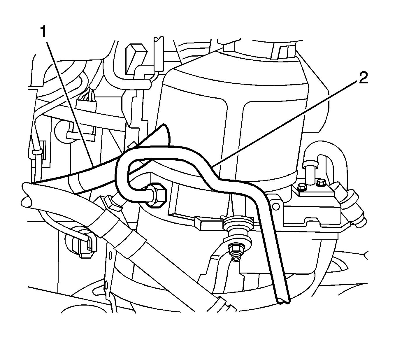
Note: Oil runs out, use a drain pan.
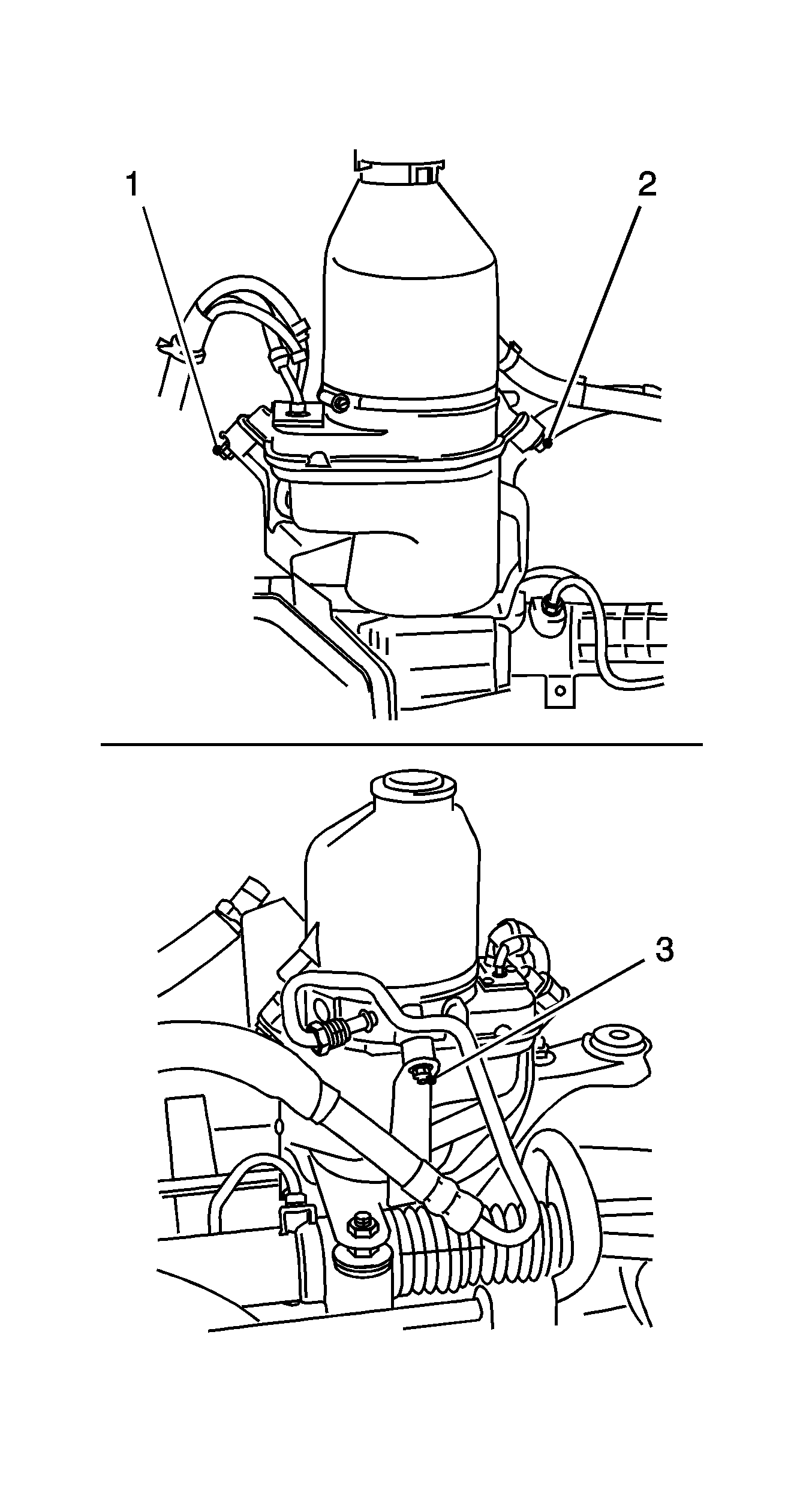
Remove the 3 nuts (1-3) from the holder.
Note: Remove the electro-hydraulic supply unit upwards.
Installation Procedure
- Insert the electro-hydraulic supply unit in the bracket.
- Position the wiring harness and attach to the front frame.
- Tighten the retaining nut.
- Install the right engine splash shield.
- Connect the steering wiring harness.
- Attach the coolant surge tank to the holder.
- Install the battery tray. Refer to Battery Tray Replacement.
- Install the battery. Refer to Battery Replacement.
- Fit the bleed hose to the tank bleed valve.
- Install the air cleaner housing. Refer to Air Cleaner Assembly Replacement.
- Connect the battery ground terminal.
- Fill the power steering. Refer to Checking and Adding Power Steering Fluid.
- Charge and bleed the hydraulic system. Refer to Power Steering System Bleeding.
- For programming procedures, refer to Control Module References.
Caution: Refer to Fastener Caution in the Preface section.
Note: Note steering wiring harness.
Attach the electro-hydraulic supply unit to the bracket.
Tighten
Tighten the 3 nuts to 7 N·m (62 lb in).
Note: Ensure the wiring is routed properly.
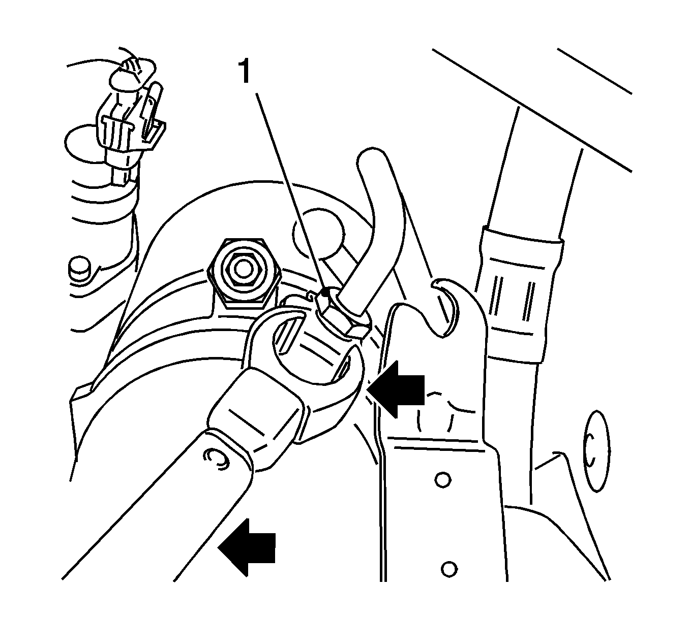
Tighten
Tighten the nut to 30 N·m (22 lb ft).

| • | Position the steering wiring harness. |
| - | Attach the cable ties. |
| - | Clip the wiring harness into the brackets. |
| • | Detach the cover from the positive distribution. |
| • | Attach the wiring harness to fixing (1). |
| • | Connect the wiring harness plug for steering (2). |
| • | Attach the ground cable (3) for the steering wiring harness to the ground pole terminal. |
Note: Do not connect the battery ground at this point.
| • | Connect the quick-acting closure. |
| • | Clip into the bracket. |
Tighten
Tighten to 5 N·m (44 lb in).
