For 1990-2009 cars only
Tools Required
J 36850 Transjel Lubricant
Removal Procedure
- Remove the battery tray. Refer to Battery Tray Replacement .
- Disconnect the air duct hose to the intake plenum. Refer to Air Cleaner Outlet Resonator Replacement or Air Cleaner Outlet Duct Replacement .
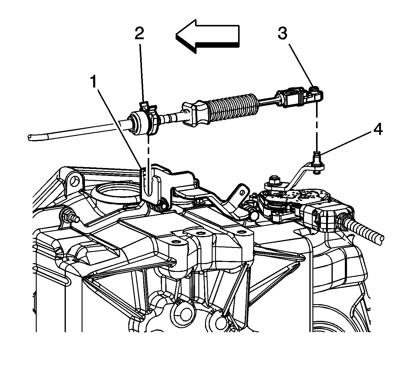
- Disconnect the shift control cable (3) from the range select lever (4).
- Release the shift control cable retaining clip (2) and remove the cable from the shift control cable bracket (1).
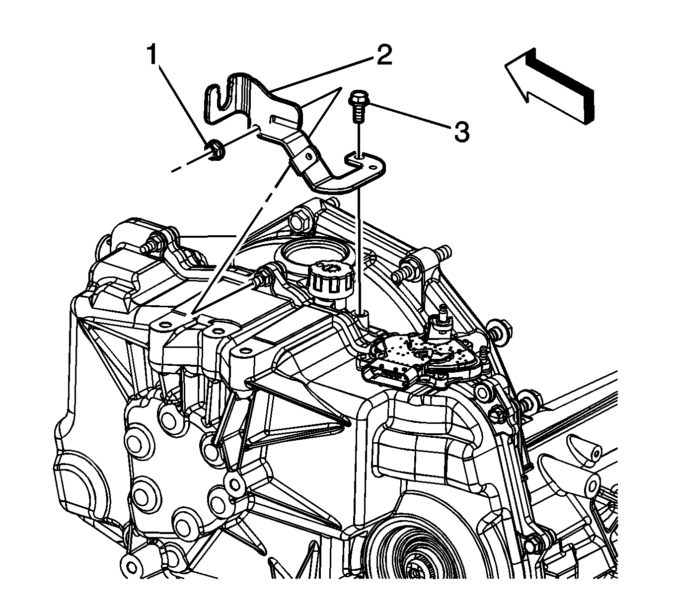
- Remove the shift cable bracket bolt (3), nut (1), and bracket (2).
- Remove the PNP switch. Refer to Park/Neutral Position Switch Replacement .
- Install the engine support fixture. Refer to Engine Support Fixture .
- Tie the radiator, air conditioning condenser, and fan module assembly to the upper radiator support to keep the assembly with the vehicle when the frame is lowered.
- If equipped with 2.4L (LAT), remove the auxiliary fluid pump. Refer to Auxiliary Fluid Pump Replacement .
- Raise the vehicle. Refer to Lifting and Jacking the Vehicle .
- Remove the left front tire and wheel. Refer to Tire and Wheel Removal and Installation .
- Remove the left front splash shield. Refer to Engine Splash Shield Replacement .
- Separate the left ball joint from the steering knuckle. Refer to Lower Control Arm Ball Joint Replacement .
- Disconnect the left tie rod from the steering knuckle. Refer to Rack and Pinion Outer Tie Rod End Replacement .
- Disconnect the left stabilizer shaft link from the stabilizer shaft. Refer to Stabilizer Shaft Link Replacement .
- Remove the left wheel drive shaft from the transmission. Refer to Front Wheel Drive Shaft Replacement .
- Remove the power steering gear intermediate shaft pinch bolt. Refer to Intermediate Steering Shaft Replacement .
- Remove the front transmission mount. Refer to Transmission Front Mount Replacement .
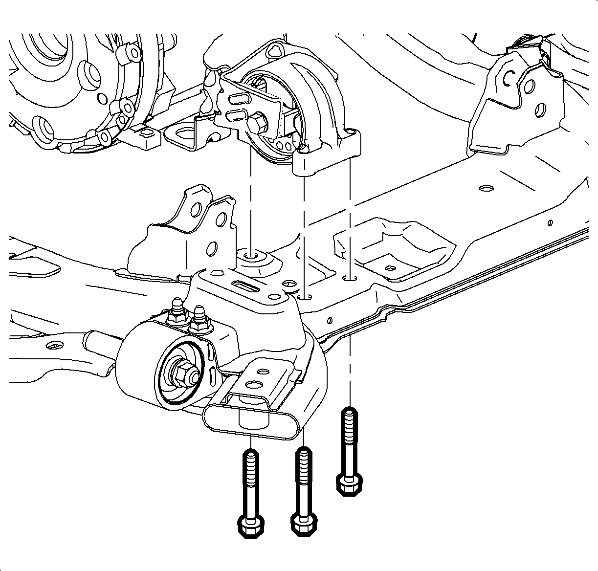
- Remove the rear transmission mount to frame bolts.
- Remove the frame bolts and lower the frame allowing the frame to hang from the right side suspension components. Refer to Frame Replacement .
- Lower the vehicle.
- Remove the left transmission mount. Refer to Transmission Mount Replacement - Left Side .
- Lower the engine and transmission with the engine support fixture until the transmission side cover will clear the inner fender.
- Raise the vehicle.
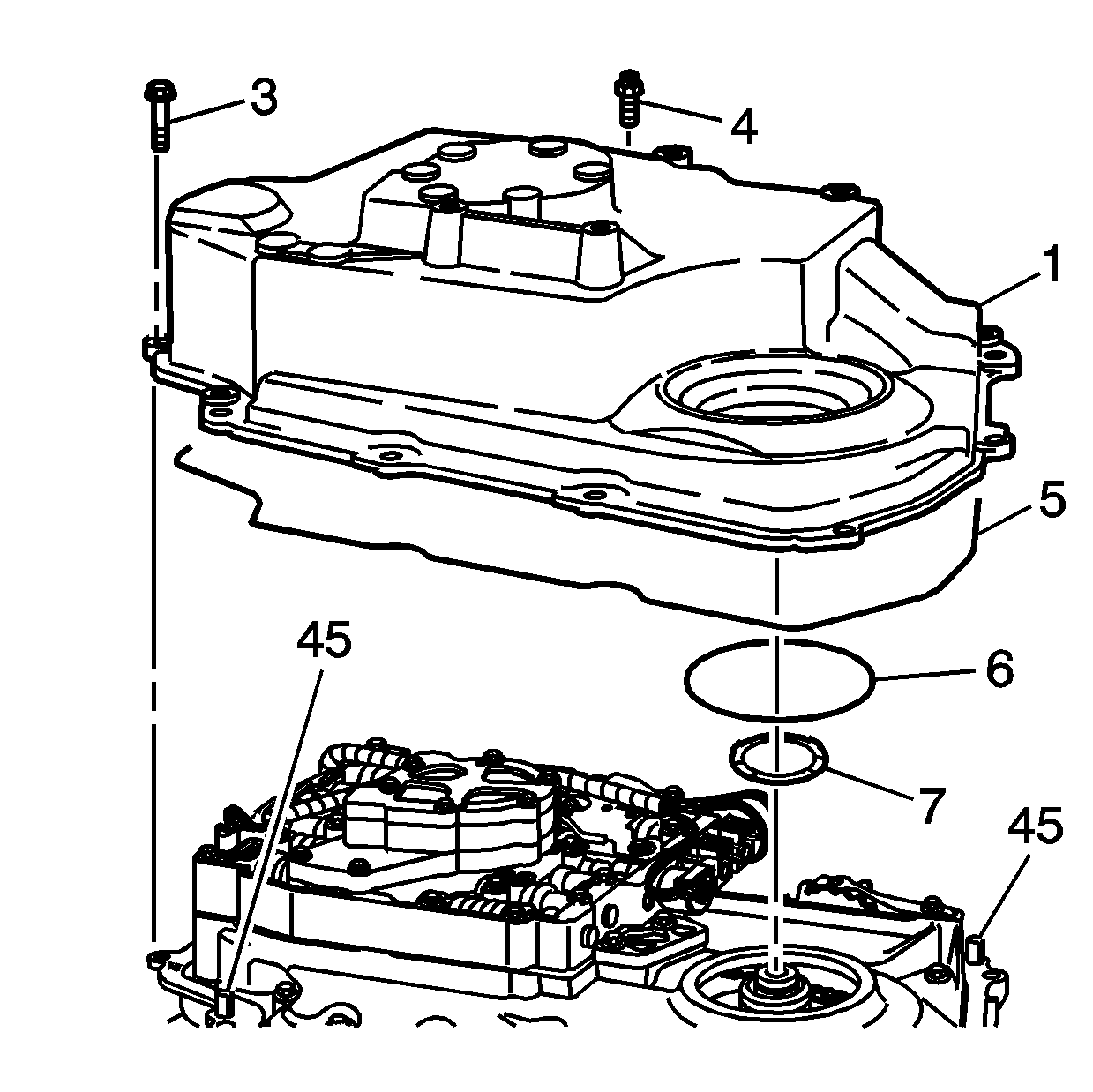
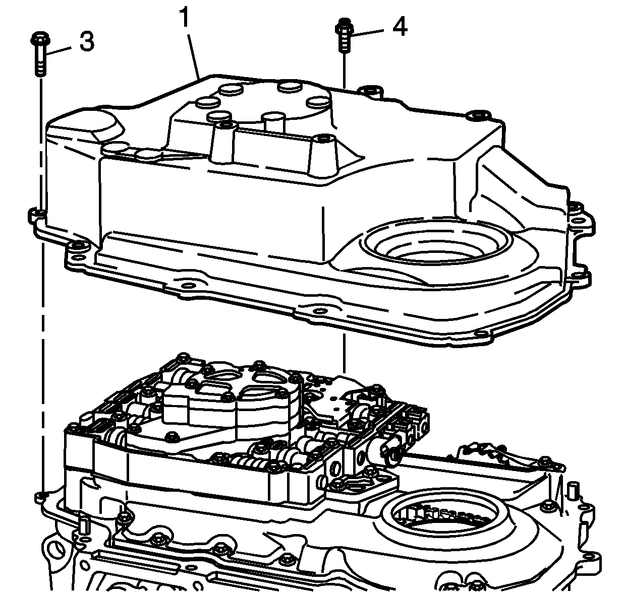
- Remove the transmission side cover bolts (3) and studs (4).
- Separate the case side cover (1) from the transmission case at the dowel pin locations (45) to prevent damage to the sealing surfaces.
- Remove the transmission side cover (1).
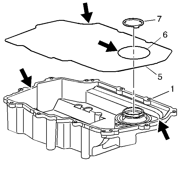
- Remove the two side cover gaskets (5 and 6) if they do not remain with the side cover.
- Remove the thrust washer (7) if it does not remain with the side cover.
- Remove the side cover axle seal (2). Use the handle end of a hammer.
- Remove the sleeve from the output axle shaft. Refer to Front Wheel Drive Shaft Seal and Output Shaft Sleeve Replacement - Left Side .
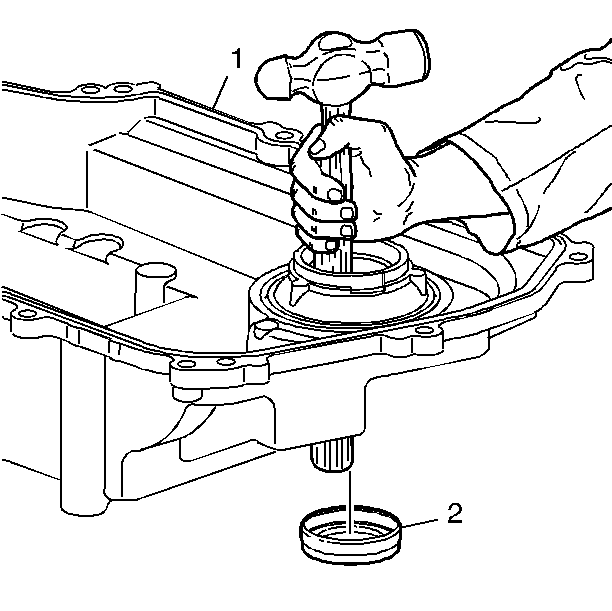
Notice: Do not damage the case bore when removing the axle seal.
Installation Procedure
- Inspect the side cover for cracks or damage to the seal grooves and mounting bosses.
- Inspect the side cover seals for damage. The side cover seals are reusable if not damaged.
- Thoroughly clean the side cover and the side cover seals.
- Clean and dry the seal grooves and the axle seal bore.
- Install the side cover gaskets (5 and 6) into the grooves on the side cover (1).
- Retain the seals with J 36850 or equivalent.
- Install the side cover to drive sprocket thrust washer (7) onto the side cover.
- Retain the thrust washer with J 36850 or equivalent.
- Install the transmission side cover (1) to the transmission case.
- Install the transmission side cover bolts (3) and studs (4).
- Install the output axle seal and sleeve. Refer to Front Wheel Drive Shaft Seal and Output Shaft Sleeve Replacement - Left Side .
- Lower the vehicle.
- Raise the engine and transmission with the engine support fixture.
- Install the transmission mount. Refer to Transmission Mount Replacement - Left Side .
- Raise the vehicle.
- Install the frame bolts. Refer to Frame Replacement .
- Install the rear transmission mount to frame bolts.
- Install the front transmission mount. Refer to Transmission Front Mount Replacement .
- Install the power steering gear intermediate shaft pinch bolt. Refer to Intermediate Steering Shaft Replacement .
- Install the left wheel drive shaft to the transmission. Refer to Front Wheel Drive Shaft Replacement .
- Connect the left ball joint to the steering knuckle. Refer to Lower Control Arm Ball Joint Replacement .
- Connect the left tie rod to the steering knuckle. Refer to Rack and Pinion Outer Tie Rod End Replacement .
- Connect the left stabilizer shaft link to the stabilizer shaft. Refer to Stabilizer Shaft Link Replacement .
- Install the left front splash shield. Refer to Engine Splash Shield Replacement .
- Install the left front tire and wheel. Refer to Front Wheel Drive Shaft Replacement .
- If equipped with 2.4L (LAT), install the auxiliary fluid pump. Refer to Auxiliary Fluid Pump Replacement .
- Lower the vehicle. Refer to Lifting and Jacking the Vehicle .
- Untie the radiator, air conditioning condenser, and fan module assembly.
- Remove the engine support fixture. Refer to Engine Support Fixture for the 2.2L (L61) engine.
- Install the PNP switch. Refer to Park/Neutral Position Switch Replacement .
- Install the shift cable bracket (2), bolt (3), and nut (1).
- Install the shift control cable to the shift control cable bracket (1). Ensure the cable retaining clip (2) is fully seated.
- Connect the shift control cable (3) to the range select lever (4).
- Connect the air duct hose to the intake plenum. Refer to Air Cleaner Outlet Resonator Replacement for the 2.2L (L61) engine or Air Cleaner Outlet Duct Replacement for the 2.4L (LAT) engine.
- Install the battery tray. Refer to Battery Tray Replacement .
- Fill the transmission. Refer to Approximate Fluid Capacities .
- Using a scan tool, prime the transmission auxiliary pump.
Notice: Refer to Fastener Notice in the Preface section.
Tighten
Tighten the bolts and studs to 28 N·m (22 lb ft).

Tighten
Tighten the bolts to 50 N·m (37 lb ft).

Tighten
Tighten the bolt (3) and nut (1) to 22 N·m (16 lb ft).

Notice: Transmission Auxiliary Pump Priming must be performed after any service procedure is performed on the transmission that involves the draining of and refill of transmission fluid. Failure to perform the Transmission Auxiliary Pump Priming will result in damage to the auxiliary pump and possible damage to the transmission.
