Removal Procedure
- LOCK the steering column. Verify the front wheels are in the straight ahead position.
- Remove the left instrument panel (I/P) lower trim panel retainer. Refer to Instrument Panel Retainer Replacement in Instrument Panel, Gages, and Console.
- Remove the I/P outer cover. Refer to Instrument Panel Outer Trim Cover Replacement in Instrument Panel, Gages, and Console.
- Remove the left side ventilation ducts. Refer to Instrument Panel Air Outlet Ducts Replacement in Heating, Ventilation, and Air Conditioning.
- Remove the trim covers from the steering column. Refer to Steering Column Trim Covers Replacement .
- Remove the inflatable restraint steering wheel module. Refer to Inflatable Restraint Steering Wheel Module Replacement in SIR.
- Remove the steering wheel. Refer to Steering Wheel Replacement .
- Remove the SIR coil. Refer to Inflatable Restraint Steering Wheel Module Coil Replacement in SIR.
- Remove the ignition lock cylinder. Refer to Ignition Lock Cylinder Replacement .
- Remove the ignition switch and the ignition lock cylinder solenoid, if equipped. Refer to Ignition and Start Switch Replacement .
- Remove the multifunction turn signal switch. Refer to Turn Signal Multifunction Switch Replacement .
- Remove the windshield wiper and washer switch. Refer to Windshield Wiper and Washer Switch Replacement in Wipers/Washer Systems.
- Loosen, but do not remove, the bolts that retain the steering column to the I/P.
- Raise and support the vehicle. Refer to Lifting and Jacking the Vehicle in General Information.
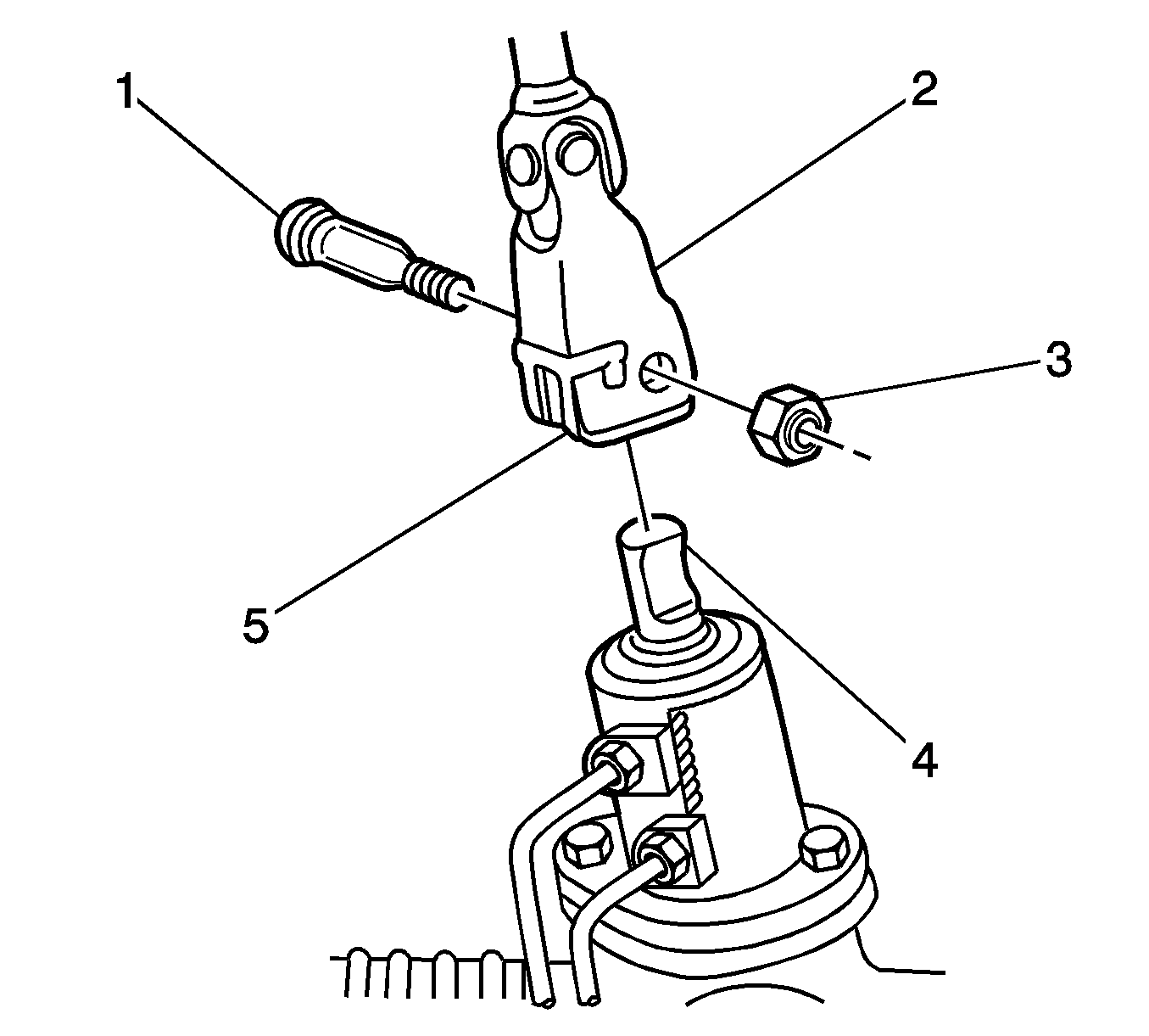
- Remove and discard the nut (3) that retains the steering shaft coupling (2) to the steering gear pinion (4).
- Remove the bolt (1) from the coupling.
- Separate the coupling from the pinion.
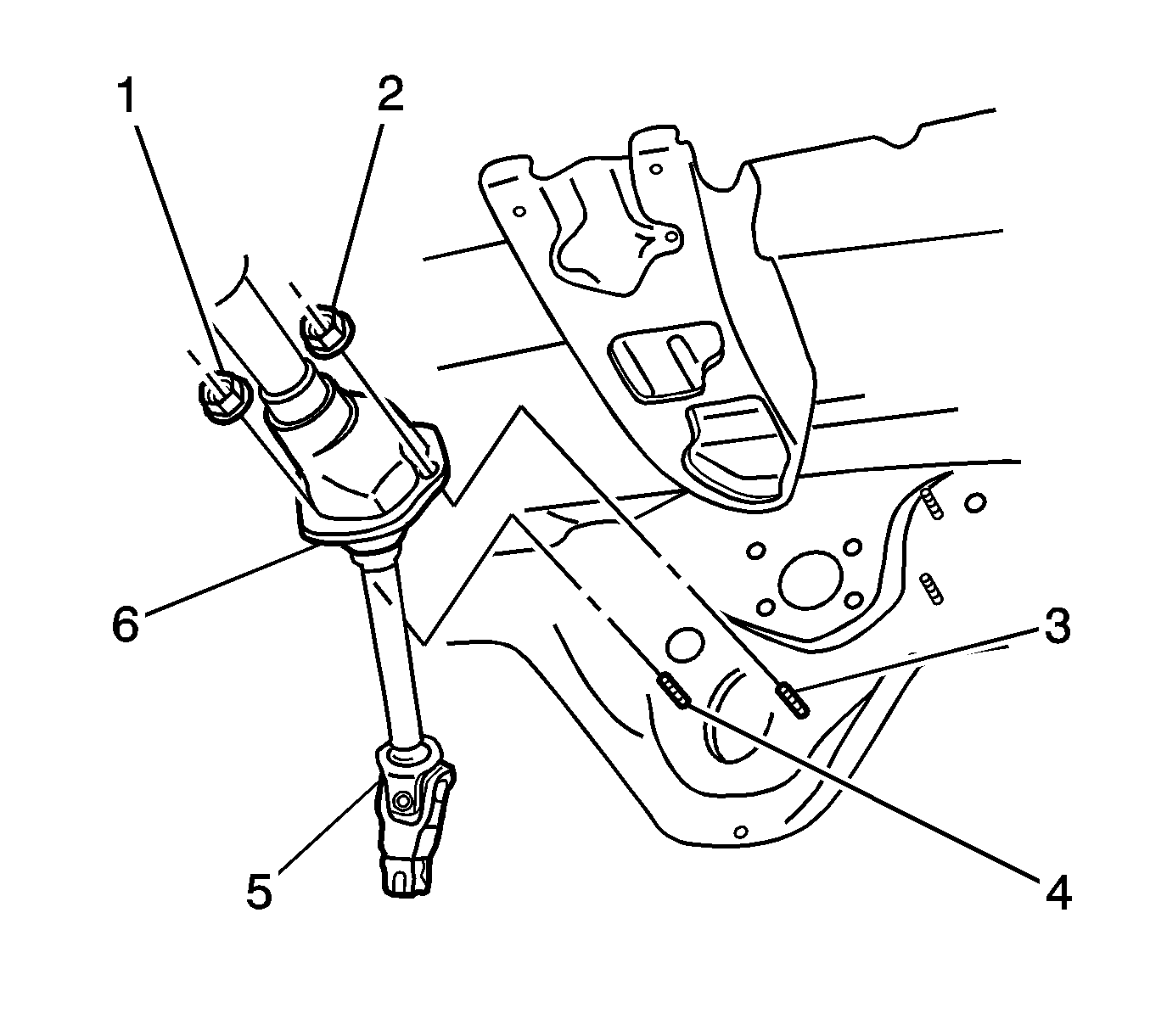
- Inside the vehicle, remove the 2 nuts (1,2) from the lower column.
- Support the column and remove the bolts from the upper column.
- Remove the column from the vehicle.
Notice: Refer to Steering Column in Lock Position Notice in the Preface section.


Notice: Once the steering column is removed from the vehicle, the column is extremely susceptible to damage. Dropping the column assembly on the end could collapse the steering shaft or loosen the plastic injections, which maintain column rigidity. Leaning on the column assembly could cause the jacket to bend or deform. Any of the above damage could impair the columns collapsible design. Do NOT hammer on the end of the shaft, because hammering could loosen the plastic injections, which maintain column rigidity. If you need to remove the steering wheel, refer to the Steering Wheel Replacement procedure in this section.
Installation Procedure
- Verify the front tires have not moved since the removal of the steering column.
- Inspect the foam seal on the lower steering column housing (6).
- Place the column inside the vehicle.
- Install the bottom of the column through the hole in the floor. Install, but do not tighten, the 2 nuts (1,2) in order to retain the lower portion of the column.
- Install, but do not tighten, the 2 bolts in order to retain the upper portion of the column.
- Install the steering shaft coupling (2) to the steering gear pinion (4).
- Install the bolt (1) to the coupling. Install a NEW nut (3) to the bolt.
- Tighten the 2 nuts (1,2) on the lower portion of the column.
- Tighten the 2 bolts on the upper portion of the column.
- Install the windshield wiper and washer switch. Refer to Windshield Wiper and Washer Switch Replacement in Wipers/Washer Systems.
- Install the multifunction turn signal switch. Refer to Turn Signal Multifunction Switch Replacement .
- Install the ignition switch and the ignition lock cylinder solenoid, if equipped. Refer to Ignition and Start Switch Replacement .
- Install the ignition lock cylinder. Refer to Ignition Lock Cylinder Replacement .
- If necessary, center the SIR coil. Refer to Inflatable Restraint Steering Wheel Module Coil Centering .
- Install the SIR coil. Refer to Inflatable Restraint Steering Wheel Module Coil Replacement in SIR.
- Install the steering wheel. Refer to Steering Wheel Replacement .
- Install the inflatable restraint steering wheel module. Refer to Inflatable Restraint Steering Wheel Module Replacement in SIR.
- Install the trim covers to the column. Refer to Steering Column Trim Covers Replacement .
- Install the left side ventilation ducts. Refer to Instrument Panel Air Outlet Ducts Replacement in Heating, Ventilation, and Air Conditioning.
- Install the I/P outer cover. Refer to Instrument Panel Outer Trim Cover Replacement in Instrument Panel, Gages, and Console.
- Install the left I/P lower trim panel retainer. Refer to Instrument Panel Retainer Replacement in Instrument Panel, Gages, and Console.
- Lower the vehicle.

If the seal is not effective, apply a continuous bead of RTV 732, or the equivalent silicone sealant.
Important: Do not tighten the nuts or the bolts yet.

Notice: Refer to Fastener Notice in the Preface section.
Caution: In order to ensure the intended function of the steering
column in a vehicle during a crash and in order to avoid personal injury to
the driver, perform the following:
• Tighten the steering column lower fasteners before you tighten
the steering column upper fasteners. Failure to do this can damage the steering
column. • Tighten the steering column fasteners to the specified torque.
Overtightening the upper steering column fasteners could affect the steering
column collapse.
Tighten
Tighten the nut to 28 N·m (20 lb ft).

Tighten
Tighten the nuts to 23 N·m (17 lb ft).
Tighten
Tighten the bolts to 23 N·m (17 lb ft).
