Tools Required
EN 46114 Engine Lift Brackets
Removal Procedure
- Disconnect the battery negative cable. Refer to Battery Negative Cable Disconnection and Connection .
- Remove the throttle body air inlet duct. Refer to Air Cleaner Inlet Duct Replacement .
- Disconnect the battery negative cable from the engine block. Refer to Battery Negative Cable Replacement .
- Disconnect the battery positive cable from the generator and the starter. Refer to Battery Positive Cable Replacement .
- Drain the cooling system. Refer to Cooling System Draining and Filling .
- Disconnect the radiator hoses from the engine. Refer to Radiator Inlet Hose Replacement and Radiator Outlet Hose Replacement .
- Disconnect the heater hoses from the engine. Refer to Heater Inlet Hose Replacement and Heater Outlet Hose Replacement .
- Remove the engine mount struts. Refer to Engine Mount Strut Replacement - Left Side and Engine Mount Strut Replacement - Right Side .
- Disconnect the fuel pressure and evaporative emission (EVAP) pipes from the engine. Refer to Metal Collar Quick Connect Fitting Service and Plastic Collar Quick Connect Fitting Service .
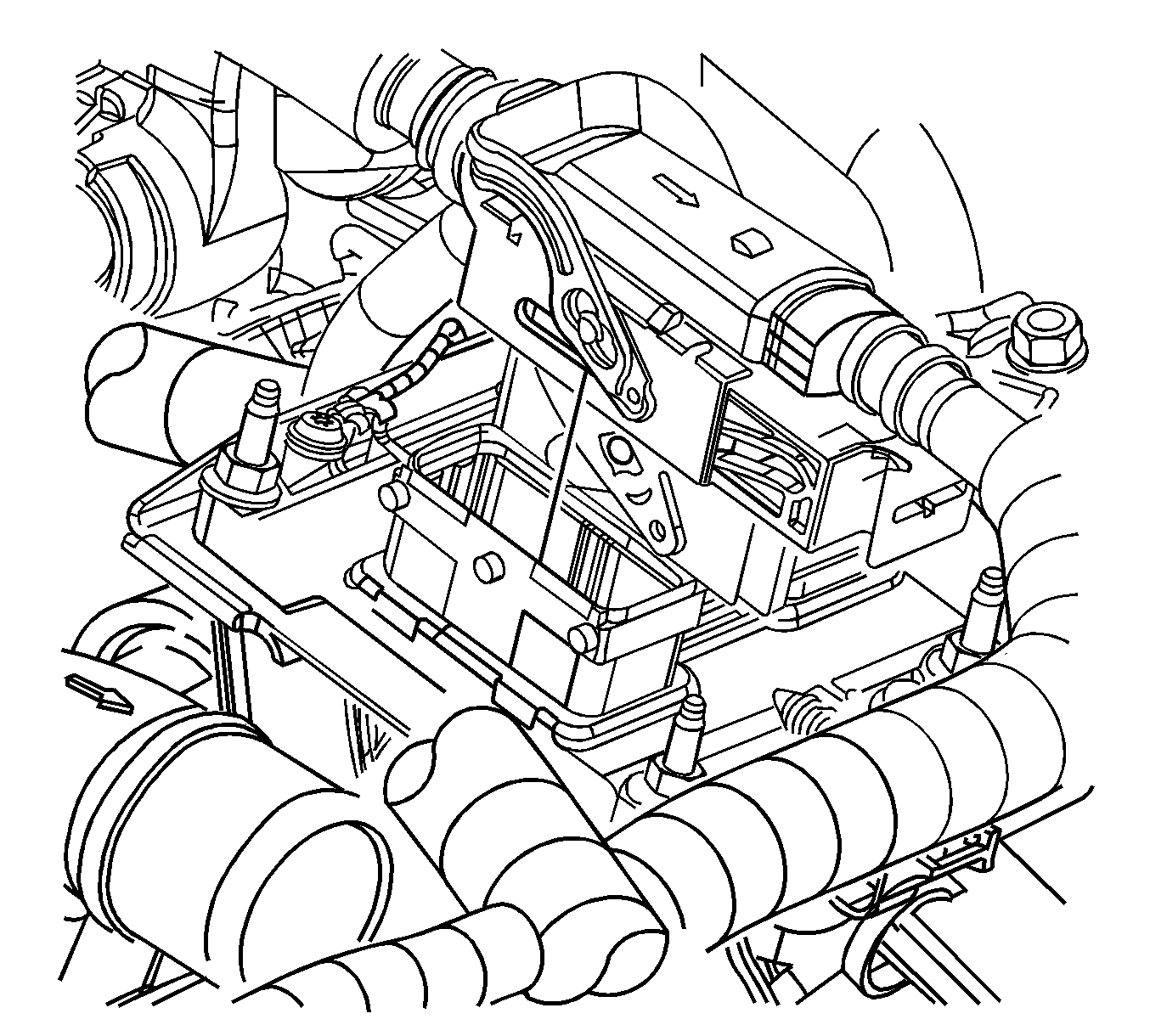
- Remove the engine control module (ECM) chassis (outboard) side electrical connector from the ECM.
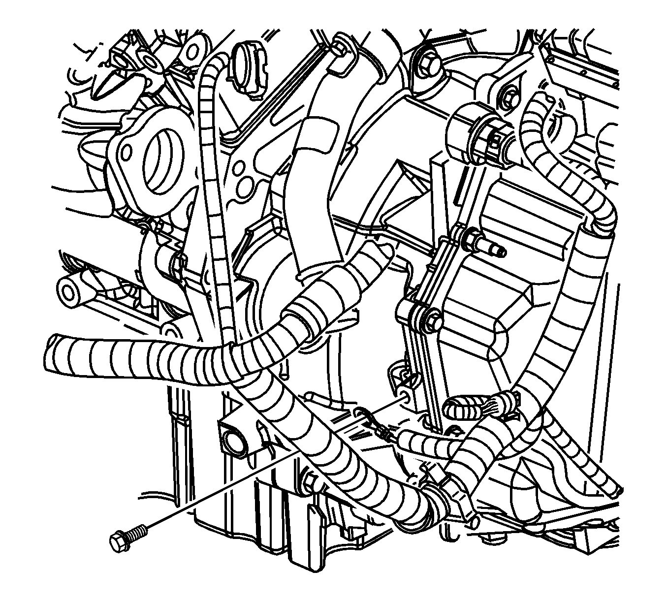
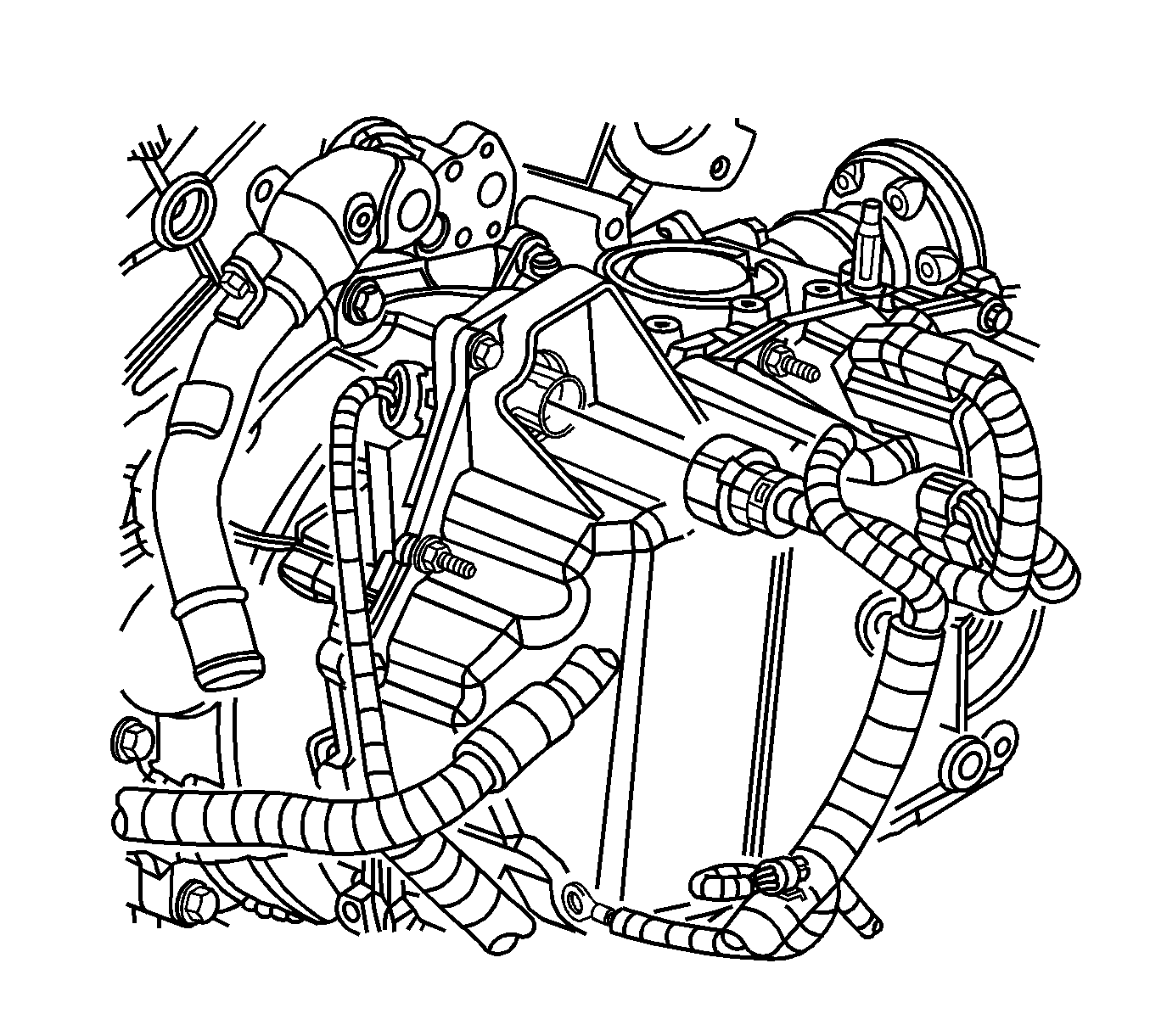
- Remove the wiring harness ground from the transmission.
- Remove the vacuum brake booster hose from the intake manifold.
- Evacuate the air conditioning system. Refer to Refrigerant Recovery and Recharging .
- Disconnect the discharge hose from the condenser. Refer to Discharge Hose Replacement .
- Disconnect the suction hose from the evaporator outlet tube. Refer to Suction Hose Replacement .
- Secure the discharge and suction hoses to the powertrain.
- Remove the transmission electrical connector.
- Raise and support the vehicle. Refer to Lifting and Jacking the Vehicle .
- If you will be separating the engine from the transmission, remove the torque converter bolts. Refer to Flywheel to Torque Converter Bolt Replacement .
- Drain the engine oil. Refer to Engine Oil and Oil Filter Replacement .
- If the vehicle is equipped with all wheel drive (AWD), remove rear propeller shaft. Refer to Propeller Shaft Replacement .
- Remove the catalytic converter. Refer to Catalytic Converter Replacement .
- Remove the front tires and wheels. Refer to Tire and Wheel Removal and Installation .
- Remove lower radiator air baffle. Refer to Radiator Air Baffle Assemblies and Deflectors .
- Remove the engine splash shields. Refer to Engine Splash Shield Replacement .
- Disconnect the vehicle speed sensor (VSS) electrical connector and secure the wiring harness to the vehicle.
- Remove the front wheel speed sensor wiring harnesses from the lower control arms and the frame.
- Remove the tie rod ends from the steering knuckles. Refer to Steering Knuckle Replacement .
- Remove the lower ball joints from the knuckles. Refer to Lower Control Arm Ball Joint Replacement .
- Disconnect the drive axles from the transaxle. Refer to Front Wheel Drive Shaft Replacement .
- Rotate the struts and reposition the drive axles toward the rear of the vehicle in order to provide clearance for the powertrain to be removed.
- Separate the intermediate steering shaft from the steering gear. Refer to Intermediate Steering Shaft Replacement .
- Remove the engine mount lower nuts. Refer to Engine Mount Replacement - Right Side .
- Remove the transmission mount lower nuts. Refer to Transmission Mount Replacement - Left Side .
- Position a powertrain lift table below the powertrain.
- Lower the vehicle until the powertrain is supported by the powertrain lift table.
- Remove the frame bolts. Refer to Front Frame Replacement .
- Carefully raise the vehicle or lower the powertrain table in order to remove the powertrain from the vehicle.
- Remove the exhaust crossover pipe. Refer to Exhaust Crossover Pipe Replacement .
- Remove the coolant inlet pipe. Refer to Radiator Inlet Hose Replacement .
- Perform the following steps if it is necessary to separate the engine from the transmission.
- Use 4 M1 0x1.5x40 GM P/N 11519182, or equivalent bolts to install the EN 46114 engine lift brackets to the left rear and right front cylinder heads.
- Use an engine hoist in order to separate the engine from the transmission and the frame.
- Install the engine to a suitable engine stand.
- Refer to the appropriate service information in order to remove the necessary components from the engine.
Important: Do not disconnect the battery negative cable from the vehicle.
Important: Do not disconnect the battery positive cable from the vehicle, underhood electrical center or the battery.
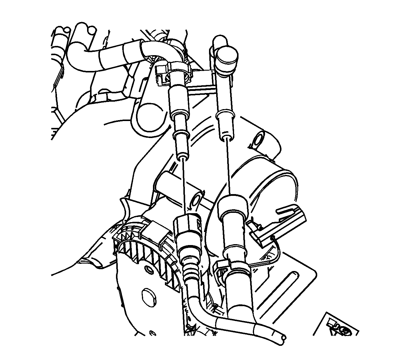
Important: Relieve the fuel pressure. Refer to Fuel Pressure Relief .
Caution: Failure to disconnect the intermediate shaft from the rack and pinion steering gear stub shaft can result in damage to the steering gear and/or intermediate shaft. This damage may cause loss of steering control which could result in an accident and possible personal injury
| Important: Do not disconnect the power steering pipes or drain the power steering fluid. |
| 41.1. | Remove the power steering pressure pipe/hose from the water outlet. Refer to Power Steering Pressure Pipe/Hose Replacement . |
| 41.2. | Remove the accessory drive belt. Refer to Drive Belt Replacement . |
| 41.3. | Remove the power steering reservoir and reposition to provide access. Refer to Remote Power Steering Fluid Reservoir Replacement . |
| 41.4. | Remove and reposition the power steering pump with the power steering pipe/hose. Refer to Power Steering Pump Removal . |
| 41.5. | Remove the transfer case brace. Refer to Support Brace Replacement . |
| 41.6. | Remove the transmission lower brace. Refer to Transmission Brace Replacement . |
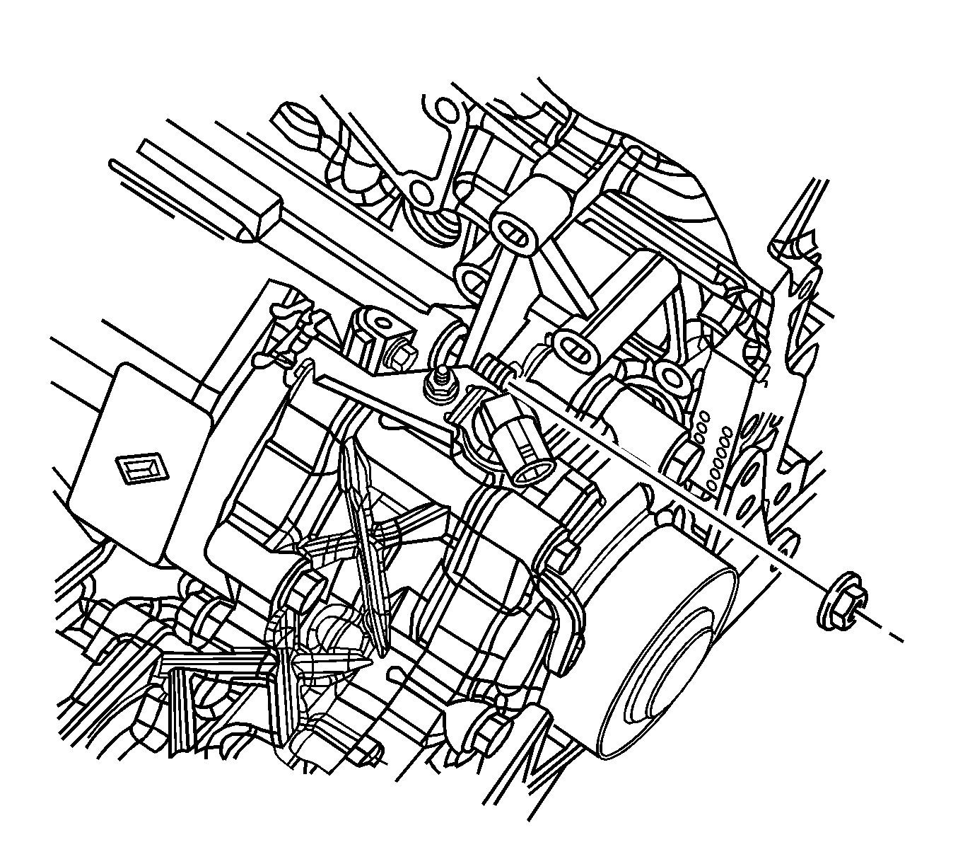
| 41.7. | Remove the transmission upper brace nut located behind the power steering pump. |
| 41.8. | Remove the engine to transmission (bell housing) bolts. Refer to Transmission Replacement . |
Notice: Refer to Fastener Notice in the Preface section.
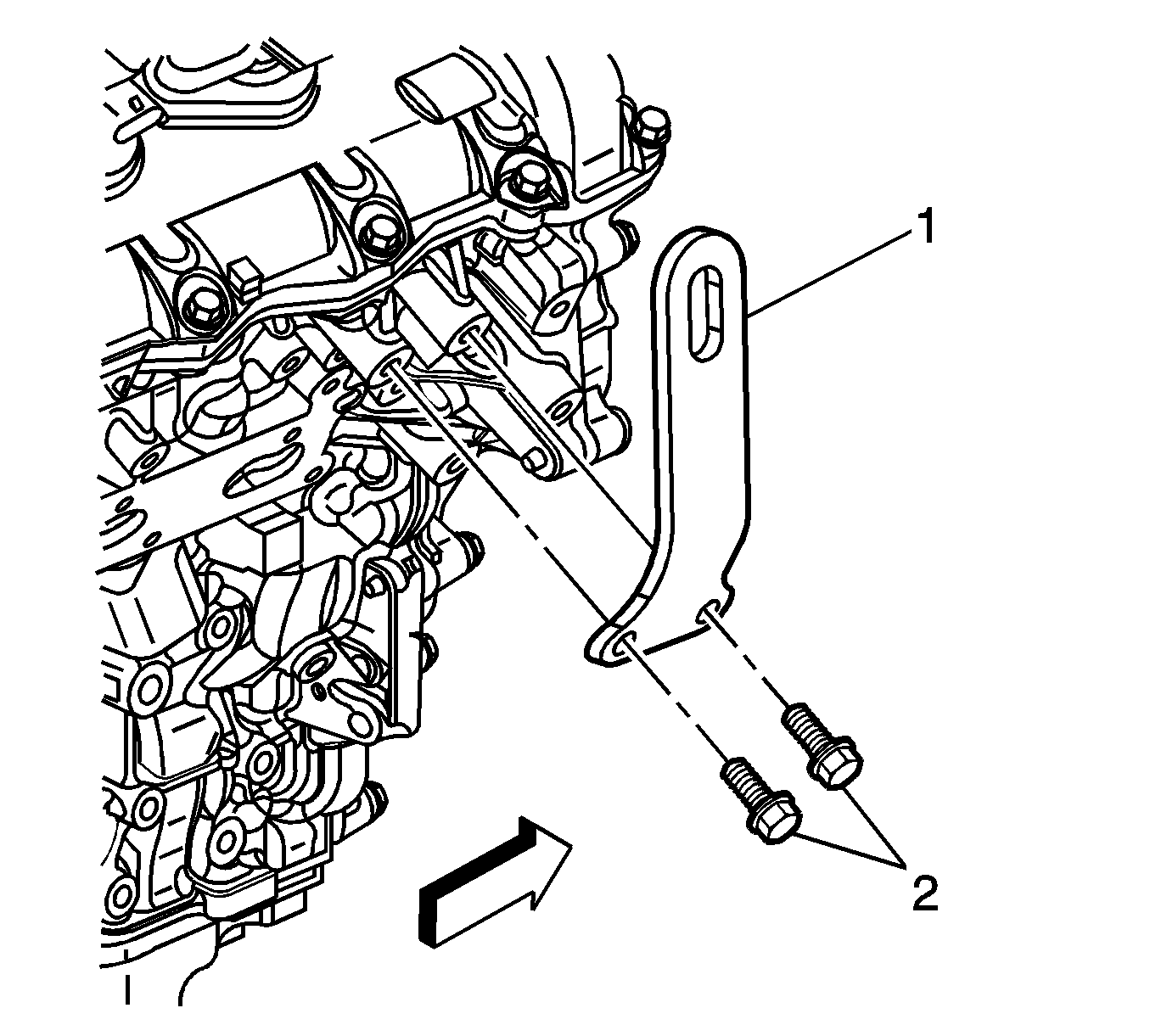
Tighten
Tighten the lift bracket bolts to 65 N·m (48 lb ft).
Installation Procedure
- Refer to the appropriate service information in order to install the necessary components to the engine.
- Use an engine hoist in order to remove the engine from the engine stand.
- Install the engine to the transmission and the frame at the powertrain lift table.
- Remove the EN 46114 engine lift brackets.
- Install the engine to transmission (bell housing) bolts. Refer to Transmission Replacement .
- Install the transmission upper brace nut located behind the power steering pump.
- Install the transmission lower brace. Refer to Transmission Brace Replacement .
- Install the transfer case brace. Refer to Support Brace Replacement .
- Install the power steering pump with the power steering pipe/hose. Refer to Power Steering Pump Removal .
- Install the power steering reservoir and reposition to provide access. Refer to Remote Power Steering Fluid Reservoir Replacement .
- Install the accessory drive belt. Refer to Drive Belt Replacement .
- Install the power steering pressure pipe/hose to the water outlet. Refer to Power Steering Pressure Pipe/Hose Replacement .
- Install the coolant inlet pipe. Refer to Radiator Inlet Hose Replacement .
- Install the exhaust crossover pipe. Refer to Exhaust Crossover Pipe Replacement .
- Carefully lower the vehicle or raise the powertrain table in order to install the powertrain to the vehicle.
- Install the frame bolts. Refer to Front Frame Replacement .
- Raise the vehicle and remove the powertrain lift table.
- Install the transmission mount lower nuts. Refer to Transmission Mount Replacement - Left Side .
- Install the engine mount lower nuts. Refer to Engine Mount Replacement - Right Side .
- Install the intermediate steering shaft to the steering gear. Refer to Intermediate Steering Shaft Replacement .
- Rotate the struts and install the drive axles to the transaxle. Refer to Front Wheel Drive Shaft Replacement .
- Install the lower ball joints to the knuckles. Refer to Lower Control Arm Ball Joint Replacement .
- Install the tie rod ends to the steering knuckles. Refer to Steering Knuckle Replacement .
- Install the front wheel speed sensor wiring harnesses to the lower control arms and the frame.
- Connect the VSS electrical connector and secure the wiring harness to the vehicle.
- Install the engine splash shields. Refer to Engine Splash Shield Replacement .
- Install lower radiator air baffle. Refer to Radiator Air Baffle Assemblies and Deflectors .
- Install the front tires and wheels. Refer to Tire and Wheel Removal and Installation .
- Install the catalytic converter. Refer to Catalytic Converter Replacement .
- If the vehicle is equipped with AWD, install rear propeller shaft. Refer to Propeller Shaft Replacement .
- Install the torque converter bolts as necessary. Refer to Flywheel to Torque Converter Bolt Replacement .
- Lower the vehicle.
- Fill the engine oil as necessary. Refer to Engine Oil and Oil Filter Replacement .
- Install the transmission electrical connector.
- Connect the suction hose to the evaporator outlet pipe. Refer to Suction Hose Replacement .
- Connect the discharge hose to the condenser. Refer to Discharge Hose Replacement .
- Recharge the air conditioning system. Refer to Refrigerant Recovery and Recharging .
- Install the brake booster vacuum hose to the intake manifold.
- Install the transmission ground wire and the bolt.
- Install the ECM chassis (outboard) side electrical connector to the ECM.
- Connect the fuel pressure and EVAP pipes to the engine. Refer to Metal Collar Quick Connect Fitting Service and Plastic Collar Quick Connect Fitting Service .
- Install the engine mount struts. Refer to Engine Mount Strut Replacement - Left Side and Engine Mount Strut Replacement - Right Side .
- Connect the heater hoses to the engine. Refer to Heater Inlet Hose Replacement and Heater Outlet Hose Replacement .
- Connect the radiator hoses to the engine. Refer to Radiator Inlet Hose Replacement and Radiator Outlet Hose Replacement .
- Fill the cooling system. Refer to Cooling System Draining and Filling .
- Connect the battery positive cable to the generator and the starter. Refer to Battery Positive Cable Replacement .
- Connect the battery negative cable to the engine block. Refer to Battery Negative Cable Replacement .
- Install the throttle body air inlet duct. Refer to Air Cleaner Inlet Duct Replacement .
- Connect the battery negative cable to the battery. Refer to Battery Negative Cable Disconnection and Connection .


Tighten
Tighten the transmission upper brace nut to 50 N·m (37 lb ft).
Caution: Failure to disconnect the intermediate shaft from the rack and pinion steering gear stub shaft can result in damage to the steering gear and/or intermediate shaft. This damage may cause loss of steering control which could result in an accident and possible personal injury


Tighten
Tighten the transmission ground bolt 75 N·m (55 lb ft).


