Removal Procedure
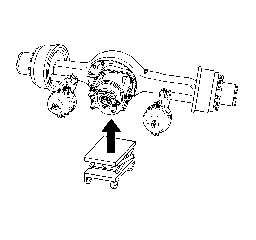
Caution: When servicing brake parts, do not create dust by grinding or sanding
brake pads, by cleaning brake parts with a dry brush or with compressed air.
Many earlier models or aftermarket brake parts may contain asbestos fibers
which can become airborne if dust is created during servicing. Breathing dust
containing asbestos fibers may cause serious bodily harm. A water dampened
cloth or water based solution should be used to remove any dust on brake parts.
Equipment is commercially available to perform this washing function. These
methods will prevent fibers from becoming airborne.
Important: Shift the two speed rear axle into LOW range, if equipped.
- Block the front wheels.
- Raise and support the vehicle under the frame rails. Ensure that
the vehicle rear wheels are off the floor. Refer to
Lifting and Jacking the Vehicle
in General Information.
- Support the rear axle housing.
| • | Use a hydraulic transmission dolly with adapters in order to properly
handle the rear axle housing. |
| • | Fasten a chain over the top of the rear axle housing and to both
sides of the hydraulic transmission dolly. |
- Release the parking brake.
- Remove the rear tire and wheel assemblies. Refer to
Wheel Removal
in Tires and Wheels.
- Remove the Axle Shaft. Refer to
Rear Hub and Bearing Replacement
.
- Remove the rear axle lubricant. Refer to
Lubricant Change
.
- Remove the propeller shaft. Refer to the following procedures
in Propeller Shaft:
- Remove the rear air brake assemblies, if equipped. Refer to
Air Brake Chamber Replacement
in Air Drum.
- Remove the rear brake caliper mounting plate, if equipped. Refer
to
Brake Caliper Mounting Plate Replacement
in Disc Brakes.
- Remove the two speed rear axle shift motor, if equipped. Refer
to
Two Speed Rear Axle Shift Motor Replacement
.
- Remove the differential lock air line, if equipped.
- Remove the wiring attached to the rear axle housing.
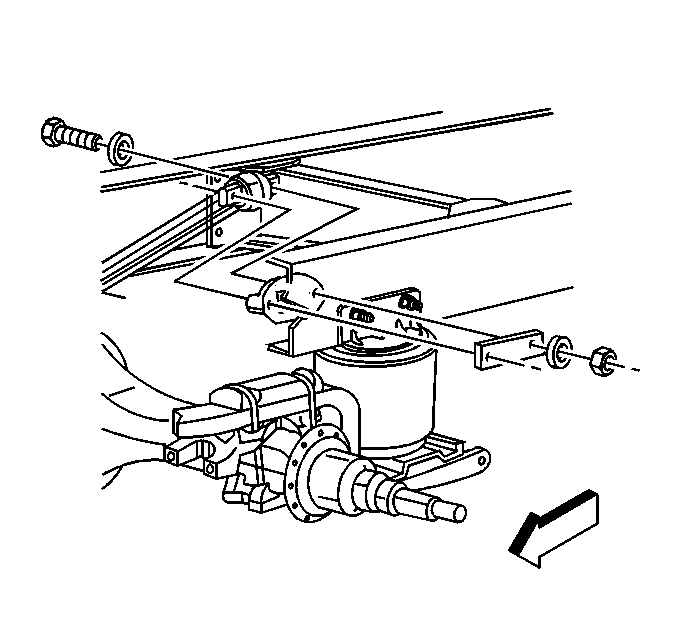
- Remove the rear axle tie
rod, if equipped.
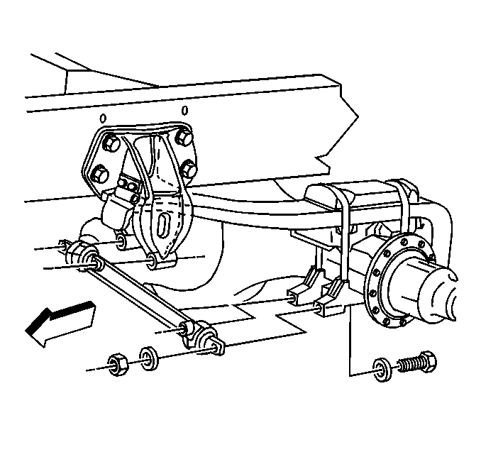
- Remove the rear suspension
control arms.
- Remove the rear shock absorber from the rear shock absorber lower
bracket.
- Remove the following components from the rear axle stabilizer
shaft. Disconnect the components only from the rear axle housing:
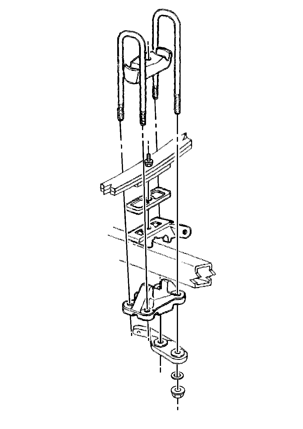
- Remove the following rear
spring components:
- Remove the rear shock absorber lower bracket, if equipped.
- Remove the rear spring anchor plate bracket.
- Remove the rear axle housing from the suspension.
- Remove the differential carrier. Complete the following steps:
| 22.1. | Set the rear axle housing on an axle stand with the differential
carrier facing up. |
| 22.2. | Remove the following differential carrier components: |
| 22.3. | Strike the differential carrier housing with a rubber mallet in
order to break the seal. |
| 22.4. | Lift the differential carrier from the rear axle housing. Use
a chain lift or equivalent. |
- Clean the differential carrier seal surface.
- Clean the rear brake drum or the rear bake rotor, and the rear
brake assemblies using Brake Parts Cleaner GM P/N 12345754 or
equivalent.
- Clean the rear wheel bearings. Refer to
Bearings Inspection
.
- Inspect the rear axle housing for the following conditions:
Installation Procedure
- Install the differential carrier. Refer to
Differential Replacement
.
- Lift the differential carrier, then lower the carrier onto the
rear axle housing. Use a chain lift or equivalent.
- Install the rear axle housing to the rear suspension.

- Support the rear axle
housing using a hydraulic transmission dolly with adapters in order to properly
handle the rear axle housing.
- Fasten a chain over the top of the rear axle housing and to both
sides of the dolly.
- Install the rear spring anchor plate bracket.
- Install the rear shock absorber lower bracket, if equipped.
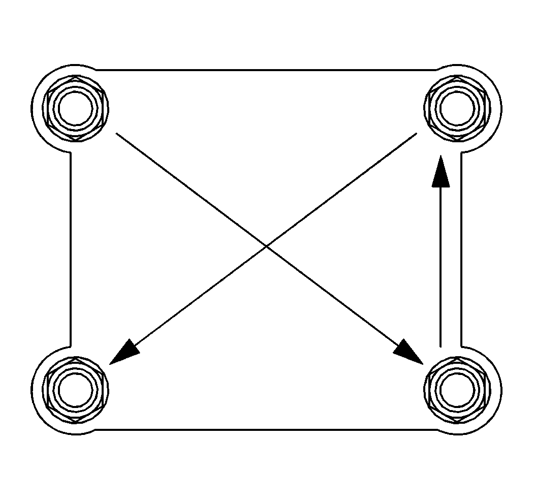
Notice: Use the correct fastener in the correct location. Replacement fasteners
must be the correct part number for that application. Fasteners requiring
replacement or fasteners requiring the use of thread locking compound or sealant
are identified in the service procedure. Do not use paints, lubricants, or
corrosion inhibitors on fasteners or fastener joint surfaces unless specified.
These coatings affect fastener torque and joint clamping force and may damage
the fastener. Use the correct tightening sequence and specifications when
installing fasteners in order to avoid damage to parts and systems.
- Install the following
components:
| • | The rear spring U-bolts |
| | Important: In order to properly tighten the rear spring U-bolt nuts, torque the
nuts progressively using the following steps:
|
| • | Tighten the rear spring U-bolt (20 mm [0.79 in] OD). |
Tighten
- Tighten the rear spring U-bolt nuts to 100 N·m (74 lb ft).
- Tighten the rear spring U-bolt nuts to 250 N·m (184 lb ft).
- Tighten the rear spring U-bolt nuts to 388 N·m (287 lb ft)
.
| • | Tighten the rear spring U-bolt (22 mm [0.87 in] OD). |
Tighten
- Tighten the rear spring U-bolt nuts to 150 N·m (111 lb ft).
- Tighten the rear spring U-bolt nuts to 275 N·m (203 lb ft).
- Tighten the rear spring U-bolt nuts to 437 N·m (344 lb ft).
- Install the rear shock absorber to the rear shock absorber lower
bracket.
Tighten
Tighten the rear shock absorber lower nuts to 84 N·m (62 lb ft).
- Install the rear axle stabilizer shaft to the axle housing, if
equipped. Refer to
Stabilizer Shaft Replacement
.
Tighten
Tighten the rear axle stabilizer shaft nuts to 240 N·m
(177 lb ft).
- Install the rear suspension control arms (air suspension only).
Tighten
Tighten the rear suspension control arm nuts to 241 N·m
(178 lb ft).
- Install the rear axle tie rod, if equipped.
Tighten
| • | Tighten the rear axle tie rod nuts (with air suspension) to 508 N·m
(375 lb ft). |
| • | Tighten the rear axle tie rod nuts (except air suspension) to
298 N·m (220 lb ft). |
- Install the differential lock air line, if equipped.
- Install the two speed rear axle shift motor, if equipped. Refer
to
Two Speed Rear Axle Shift Motor Replacement
.
- Install the wiring to the rear axle housing.
- Install the rear air brake assembly, if equipped. Refer to
Air Brake Chamber Replacement
in Air Drum
- Install the rear brake caliper mounting plates, if equipped. Refer
to
Brake Caliper Mounting Plate Replacement
in Disc Brake
- Install the propeller shaft. Refer to the following procedures:
- Install the rear axle lubricant. Refer to
Lubricant Change
.
- Install the rear tire and wheel assemblies. Refer to
Wheel Installation
in Tires and Wheels.
- Remove the Axle Shaft. Refer to
Rear Hub and Bearing Replacement
or .
- Check for air leaks. Refer to
Air Brake System Testing
in Air Brake.
- Verify proper operation of the brakes.
- Remove the wheel blocks.


